Related topics
Connection example: "safety circuit (STO)", page 56
Safety function STO: "Safety Circuit / Restart Lock (STO)", page 95
7.7 X15 – Digital Outputs
If you want to make use of the digital inputs and outputs, connect pin 9 to
24 V. You can either bridge 24 V from pin 10 of X15 (max. 0.3 A) or you
supply 24 V from an external voltage source.
In order to display the error status still after deliberately disconnecting the
mains supply, you can maintain the logic supply by connecting pin 8 to 24 V
(0.5 A).
The available functions of the digital outputs are different depending on the drive func‐
tion. You can set the desired function in the software
drivemaster2
.
7.7.1 Digital Outputs – SERVO / VECTOR
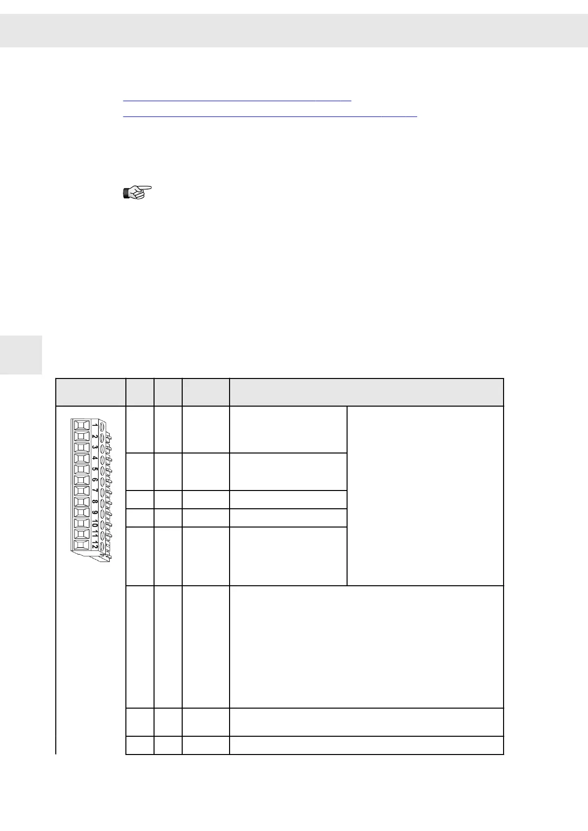
12-pole Mini-Combicon connector, suitable for mating connector MC 1,5/ 12-ST-3,81
(Phoenix)
Mating connector
X15
Pin I/O Name Configurable functions
1 O OUT0 ▶ Ready type 1 (with power
supply okay)
▶ Ready type 2 (without
power supply okay)
▶ No function
▶ M01 – Message power output stage
ready
▶ M02 – Message operation enabled
▶ M03 – Message drive error
▶ M10 – Ref. value reached
▶ M11 – Torque reached
▶ W04 – Power output stage load
▶ W05 – Motor load
▶ W07 – Motor temperature
▶ W09 – Undervoltage power output
stage
▶ W11 – Tracking error
▶ W12 – Speed error
▶ W17 – No commutation
▶ W24 – Warning threshold ’current'
▶ W26 – Warning threshold ’overload
current'
2 O OUT1 ▶ Signal motor holding
brake
▶ M12 – Speed zero
3
O OUT2 ▶ M12 – Speed zero
4 O OUT3 ▶ M12 – Speed zero
5 O OUT4 ▶ M12 – Speed zero
6 I IN8 ▶ No function
▶ Speed direction
▶ P-controller
▶ Error reset
▶ External hardware OK
▶ Low gain Kpn
▶ Docking function
▶ Teach no-load current
▶ Parameter set Bit 5
▶ MOP up
▶ MOP down
▶ Reset commutation
7 O PULSE
OUT
Speed pulses
8 I VCC EXT 24 V logic supply in the event of an AC power failure (0.5 A)
Connector Pin Assignment
W
40 Drive System SD2S - Hardware Description 0362X49xy / 0362129xy
7

 Loading...
