EasyManua.ls Logo

SIEB & MEYER SD2S 0362X49xy User Manual

SIEB & MEYER SD2S 0362X49xy
114 pages
To Next Page IconTo Next Page
To Previous Page IconTo Previous Page
Page #82 background imageLoading...
Page #82 background image
10.2 7-segment display
The 7-segment display shows status and error messages.
A status message is made up of 1 to 5 digits and displayed as sequence. All messages
end with dot behind the last digit. When the first digit is 'E.', there is a permanent error.
If the cause of an error can be specified, the display indicates the actual error code
followed by a hyphen and a one-digit sub error code.
Devices with older firmware do not feature the sub error code.
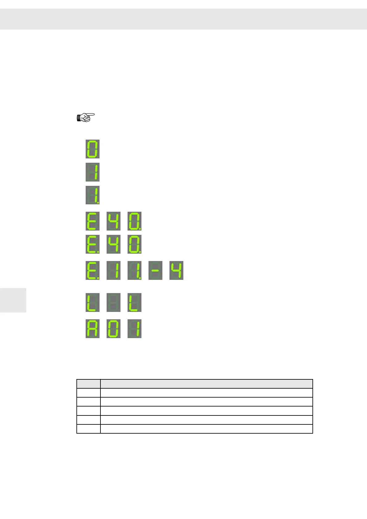
Examples:
1. Permanent display 0
Controller is switched off.
No error.
2.
Permanent display 1
Controller is switched on.
No error.
3.
Permanent display 1.
Controller is switched on.
No error.
Dot calls additional attention to PI limit.
4.
Sequential display
Controller is switched off due to error E40.
The error is not present anymore.
5.
Sequential display
Controller is switched off due to error E40.
The error is still present (indicated by the dot
behind 'E').
6.
Sequential display
Controller is switched off due to error E11.
The error is still present (indicated by the dot
behind 'E').
Sub error code 4 is indicated as cause.
7.
Sequential display
Controller is in boot loader mode: Display appears
short-time when the device is booted and when
the system software is loaded.
8.
Sequential display
Drive address: During booting of the devices the
set address of the drive is displayed short-time
(here A01)
10.2.1 List of the Operating States
Code
Description
0 Ready to switch on
1 Controller active
1. Controller active, controller is limited / PI limit
2 Mains 'Ready for operation' not present yet
L Boot loader active (during boot / software load)
Status Display and Error Messages
W
82 Drive System SD2S - Hardware Description 0362X49xy / 0362129xy
10

Table of Contents

Question and Answer IconNeed help?

Do you have a question about the SIEB & MEYER SD2S 0362X49xy and is the answer not in the manual?

SIEB & MEYER SD2S 0362X49xy Specifications

General IconGeneral
BrandSIEB & MEYER
ModelSD2S 0362X49xy
CategoryDC Drives
LanguageEnglish

Summary

About this Manual

Illustration of Warnings

Explains warning classification, signal words, and risk symbols.

Illustration of General Notices

Illustrates symbols for general notices and hints.

Technical Symbols

Defines symbols used for LED indicators.

Abbreviations

Lists abbreviations and their meanings.

General Information

Approval for the Markets in USA and Canada

Details approval requirements for USA and Canada markets.

NRTL Requirements

Lists points of exception for test procedure and conditions of acceptability.

Safety Instructions

Standards and Regulations

Lists standards and directives the devices comply with.

Working on the Device

Emphasizes safety for trained personnel during installation and maintenance.

Appropriate Use

Defines intended use, enclosure requirements, and environmental conditions.

Reasonably Foreseeable Misuse

Defines misuse according to Machinery Directive and risks.

Transport and Storage

Provides guidelines for safe transport and storage.

Installation

Covers mechanical installation conditions and operating requirements.

Electrical Connection

Details safety precautions and requirements for electrical connections.

Operation

Provides safety warnings during operation, especially regarding moving parts.

Maintenance

Recommends regular checks for cleanness and functionality.

Disposal

Advises on country-specific disposal laws and directives.

Legal Warranty

Outlines warranty terms and exclusions for damages.

Unit Assembly Complying EMC

Emission of Line and Field Interferences According to Category C3

Explains EMC requirements and meeting Category C3 limits.

Drive Amplifier SD2S

Block Diagram

Presents a functional block diagram of the SD2S drive amplifier.

Type Plate

Explains the meaning of information found on the device's type plate.

Device name

Details the structure and meaning of the device name and version.

Device Description

Dimensions

Provides detailed physical dimensions of the device.

Wall Mounting

Describes the procedure and requirements for vertical wall mounting.

Technical Data

Lists key technical specifications and performance data of the device variants.

Connectors

Details the connectors on the device, their meaning, and relevant pages.

Connector Pin Assignment

Terminal Connector Operation

Explains the operation of terminal connectors, including Click & Lock and Push-in technology.

ID switch

Describes setting the module address using the ID switch.

X6 – Encoder 0

Details the pin assignment for the X6 Encoder 0 connector.

X7 – Encoder 1 / Encoder Emulation

Details the pin assignment for the X7 Encoder 1 / Encoder Emulation connector.

X14 – USB

Details the pin assignment for the X14 USB connector for PC communication.

X10 – Safety (STO)

Details the pin assignment for the X10 Safety (STO) connector.

X15 – Digital Outputs

Details the pin assignment and functions for X15 Digital Outputs.

X16 – Digital Inputs

Details the pin assignment and functions for X16 Digital Inputs.

X17 – Motor Feedback

Details the pin assignment for the X17 Motor Feedback connector.

X18 – Analog Interface

Details the pin assignment for the X18 Analog Interface connector.

X19 – COM1 / Operating Terminal

Details the pin assignment for the X19 COM1/Operating Terminal connector.

X26/ X27 – SERVOLINK 4

Details the SERVOLINK 4 optical connectors X26 and X27.

X44 – Power Supply

Details the pin assignment for the X44 Power Supply connector.

X45 – Motor Connection

Details the pin assignment for the X45 Motor Connection connector.

X63 – External Ballast Resistor

Details the pin assignment for the X63 External Ballast Resistor connector.

X64/X65 – EtherCAT

Details the EtherCAT interface connectors X64/X65.

Connection Examples

X6, X7 – Incremental Encoder with TTL Signals

Provides a wiring example for connecting incremental encoders with TTL signals.

X7 – Encoder Emulation

Provides a wiring example for encoder emulation.

Safety Circuit (STO) Wiring

Covers wiring examples for safety circuits (STO), including OSSD and non-OSSD configurations.

X15 – Digital Outputs and Sensors

Covers wiring examples for digital outputs, NAMUR sensors, PULSE IN, and Field Plate/GMR.

X16/17 – Digital Inputs

Provides wiring examples for digital inputs at X16 and X17.

X17 – Motor Feedback Examples

Provides wiring examples for various motor feedback types connected to X17.

X18 – Analog Inputs/Outputs

Provides wiring examples for analog inputs and outputs.

X19 – Bus Connection

Covers wiring examples for bus connections, including RS232 and CAN Bus.

X26/X27 – SERVOLINK

Provides wiring example for SERVOLINK connections.

X44 – Power Supply

Provides wiring examples for power supply connections.

X45 – Motor Phases

Provides wiring examples for motor phase connections.

Shielding of the Motor Cable

Explains how to connect motor cable shielding for EMC.

X63 – External Ballast Resistor

Provides wiring example for the external ballast resistor.

X64/X65 – EtherCAT

Provides wiring example for EtherCAT connections.

Housing Ground

Explains how to ground the device housing.

Setup

SD2S Connection and Switch-on

Guides through connecting and switching on the SD2S device.

Parameter Setting and Initial Operation

Refers to manuals for parameter setting and initial device operation.

Status Display and Error Messages

LED Status Display: EtherCAT Connection

Explains the LED status indicators for EtherCAT connection.

7-Segment Display

Explains the 7-segment display for status and error messages, including operating states.

Drive Error Messages

Lists and explains drive error messages, their reactions, and possible causes.

Warning Messages

Lists warning messages that appear in drivemaster2 software.

Quick Stop Function Messages

Lists messages related to quick stop functions.

General Information Regarding the Wiring

Mains Connection

Provides important notices and guidelines for mains connection.

Cable Requirements

Details requirements for motor, signal, and communication cables.

Safety Circuit / Restart Lock (STO)

Restart Lock Functional Description

Explains the function of the restart lock and OSSD signals.

Wiring Example

Provides a wiring example for safety circuits combining emergency stop and OSSD devices.

Requirements and Standards

Lists safety parameters and standards met by the safety circuit.

Restart Lock Procedure

Illustrates the restart lock procedure with a timing diagram.

Appendix

Specification of Drive Functions

Details the available drive functions for SD2S devices.

Specification of Device Firmware

Lists available firmware variants and their supported features.

Wiring Example

Shows a comprehensive wiring example for the SD2S device.

Manufacturers and Accessories

Lists manufacturers and accessories for SIEB & MEYER products.

Index

Index

Alphabetical index of topics and their page numbers.

Related product manuals