7.11 X19 – COM1 / Operating Terminal
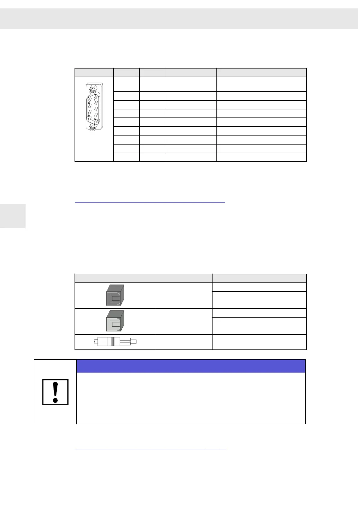
9-pole male submin D connector
X19
Pin I/O Name Meaning
1 O VCC 5.3 V (power supply for optional oper‐
ating terminal, short-circuit proof)
2 I RX Receive data
3 O TX Transmit data
4 I/O CAN_L CAN_L
5 I/O GND Ground
6 I RX2 Receive data 2
7 O TX2 Transmit data 2
8 I/O CAN_H CAN_H
9 I/O GND Ground
Stud bolt flange: max. tightening torque = 0.7 Nm
Related topics
Connection examples: "X19 – Bus Connection", page 73
7.12 X26/ X27 – SERVOLINK 4
SERVOLINK 4: optical input (X26) and optical output (X27)
The fiber optic connectors for SERVOLINK 4 are located at the bottom side of the
device.
Connector
SIEB & MEYER article number
Inputs (black)
12540102
12540103
Outputs (gray or white)
12540202
12540203
Cable connector
(TOSLINK F05)
32022900
NOTICE
Risk of cable damage
If you pull the optical fiber cable with its connector too fast out of the connector, the
cable may be damaged.
When unplugging the cable, hold the fiber optic connector and pull the cable care‐
fully out of the connector.
Related topics
Connection example: "X26/X27 – SERVOLINK", page 75
Connector Pin Assignment
W
48 Drive System SD2S - Hardware Description 0362X49xy / 0362129xy
7

 Loading...
