Mating connector
X15
Pin I/O Name Configurable functions
9 I VCC IO 24 V supply for the outputs
10 O VCC
OUT
(4)
24 V auxiliary voltage for the outputs (24 V ±10 %, uncontrolled, max.
0.25 A)
11 I/O GND Ground (pin coded)
12 I/O GND Ground
(4)
Parallel operation with other SD2S drive amplifiers or external components is not possible.
Specification of terminal connections
▶ Conductor cross-section solid/stranded: 0.14 to 1.5 mm²
▶ Tightening torque: 0.22 to 0.25 Nm
Related topics
Wiring example "Digital Outputs", page 57
Wiring example "NAMUR sensor", page 58
Wiring example "PULSE IN 24 V", page 58
Wiring example "Digital Field Plate / GMR", page 59
7.8 X16 – Digital Inputs
The available functions of the digital inputs are different depending on the drive func‐
tion. You can set the desired function in the software
drivemaster2
.
7.8.1 Digital Inputs – SERVO / VECTOR
12-pole Mini-Combicon connector, suitable for mating connector MC 1,5/ 12-ST-3,81
(Phoenix)
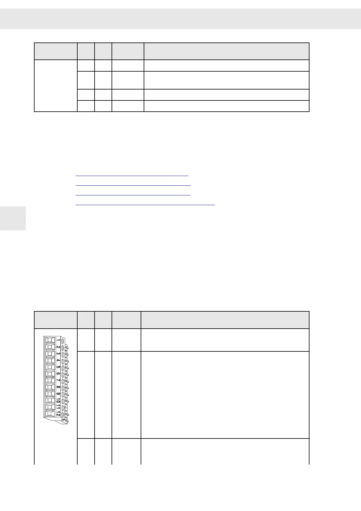
Mating connector
X16
Pin I/O Name Configurable functions
1 E IN0 ▶ No function
▶ Switch on type 1 (without edge evaluation)
▶ Switch on type 2 (with positive edge)
2
E IN1 ▶ No function
▶ Quick stop type 1 (with slow down ramp)
▶ Quick stop type 2 (with quick stop ramp)
▶ Quick stop type 3 (at current limit)
▶ Quick stop type 4 (speed enable)
▶ Quick stop type 5 (with slow down ramp and controller off)
▶ Quick stop type 6 (with quick stop ramp and controller off)
▶ Quick stop type 7 (with slow down ramp and reset)
▶ Quick stop type 8 (with quick stop ramp and reset)
▶ Enable operation
▶ Operation enabled with error reset
▶ MOP up
▶ MOP down
▶ Reducing current limitation / Imax
3 E
IN2
(1)
▶ No function
▶ Neg. limit switch type 1 (speed contr. as p-contr.)
▶ Neg. limit switch type 2 (speed contr. as pi-contr.)
▶ Enable operation
Connector Pin Assignment
W
42 Drive System SD2S - Hardware Description 0362X49xy / 0362129xy
7

 Loading...
