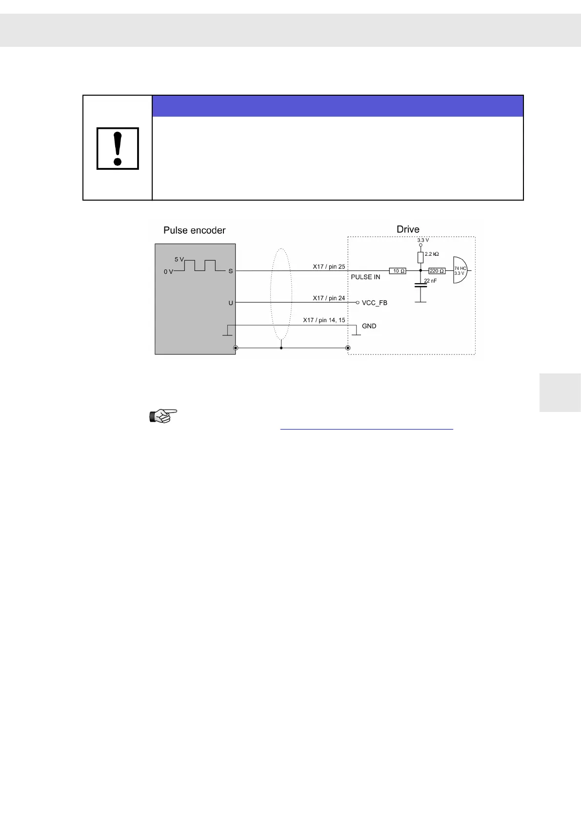
8.6.11 PULSE IN 5 V
NOTICE
Voltage (VCC) varies depending on the set measuring system
When the connected measuring system is operated under a wrong voltage, it can
be damaged.
Check that you have chosen the right measuring system in the software before
connecting.
When this meysuring system is parameterized VCC_FB is switched to 5.3 V.
A pulse generator for 24 V is to be connected at connector X15 (pin 6), see
connection example section 8.4.3 "PULSE IN 24 V", page 58.
8.6.12 Temperature Sensor of the Motor
INPUT/OUTPUT: The thermal motor protection is evaluated via these connectors.
The drive amplifier supports evaluating the temperature monitoring integrated in the
motor. The NTC/PTC behavior of the monitoring is defined in the software (motor para‐
meters). The controller is deactivated as soon as the critical motor temperature is
reached.
You can configure “None”, “PTC / Thermo switch”, “NTC”, “KTY84/130”, “KTY83/122”
and “PT1000”.
W
Connection Examples
Drive System SD2S - Hardware Description 0362X49xy / 0362129xy 71
8

 Loading...
