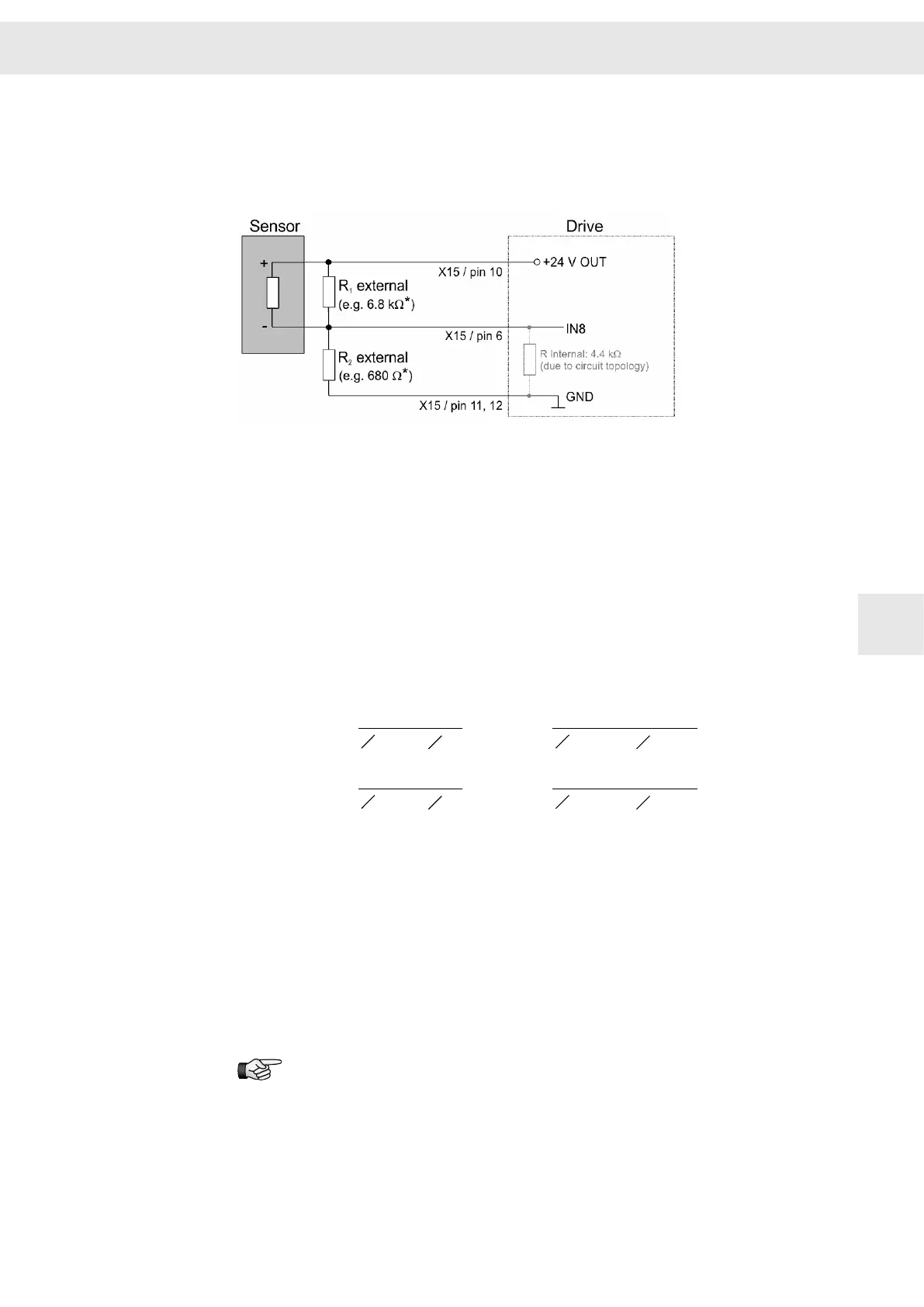
8.4.4 Digital Field Plate / GMR
The switching thresholds of the converter input IN8 are 5.4 V for active-low signals and
5.9 V for active-high signals. Therefore the switching thresholds of the used sensor
must be adapted to the input by offsetting the middle voltage.
[*] The resistors R
1
and R
2
depend on the used sensor.
Sample calculation of the resistors R
1
and R
2
The resistance is calculated by means of the spindle data.
Specifications taken from the data sheet of the spindle manufacturer:
▶ Sensor off: 4 mA (signal is not available)
▶ Sensor on: 8 mA (signal is available)
▶ Voltage V: 3 V (amplitude with 24 V supply and a resistance (R
2
) of 680 Ω)
The resistance Rinternal (4.4 kΩ) results from the circuit topology and must be
included in the calculation.
The spindle data make the following voltage levels at the input:
I
´
1
1
R
2
ext
1
Rint
+
1
1
680 W
1
4400 W
+
=
4 mA
´
=
2.36 V
Sensor off:
(
(
((
I
´
1
1
R
2
ext
1
Rint
+
1
1
680 W
1
4400 W
+
=
8 mA
´
=
4.71 V
Sensor on:
(
(
((
Middle voltage of the sensor: (4.71 V + 2.36 V) / 2 = 3.54 V
Middle voltage of the input IN8 at the SD2S: (5.9 V + 5.4 V) / 2 = 5.65 V
The voltage level must be increased according to the difference between the middle
voltages. This is done by a boost voltage at R
1
.
Boost voltage R
1
: 5.65 V - 3.54 V = 2.11 V
Resistance value R
1
: (24 V / 2.11 V) × 588 Ω = 6.688 kΩ → 6.8 kΩ
(588 Ω results from the resistances of R
2
external and Rinternal.)
If you use other sensors, please pay attention to the input switching thresh‐
olds of the sensor and the data sheet provided by the spindle manufacturer.
W
Connection Examples
Drive System SD2S - Hardware Description 0362X49xy / 0362129xy 59
8
 Loading...

