7.15 X63 – External Ballast Resistor
DANGER
High voltages in the intermediate circuit
Note that even after the device unit has been switched off high voltages may occur
in the intermediate circuit of the complete system that can cause serious injuries.
Wait until the intermediate circuit is fully discharged before cutting the connections
of the external ballast resistor ("capacitor discharge").
Take the following steps before working on the device or on the intermediate
circuit:
▶ Disconnect the device definitely from the mains supply.
▶ Wait until the discharge time of the of the DC link capacities has expired. It is
longer than 4 minutes.
▶ Ensure by measuring that the intermediate circuit is fully discharged.
▶ Disconnect the connections of the external ballast resistor from the power
supply.
▶ Also consider general safety instructions before you continue working on the
device.
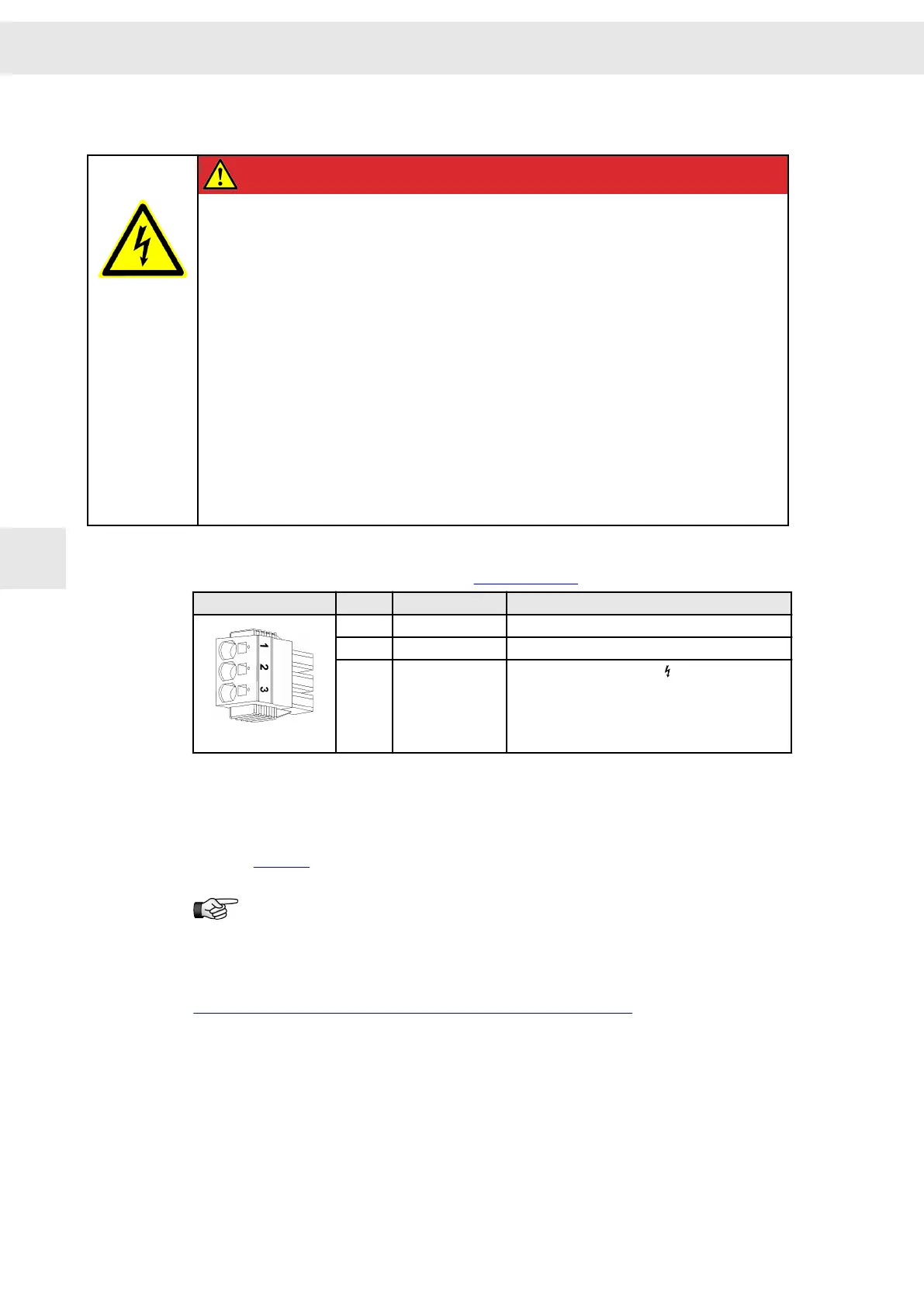
3-pole Power-Combicon connector, suitable for mating connector SPC 5/ 3-STCL-7,62
(Phoenix) with Click & Lock system (see STCL, page 37)
Mating connector X63
Pin Name Meaning
1 Rextern External ballast resistor / chopper connection
2 Rintern Internal ballast resistor
3 UB+
Positive DC link connection
Specification of terminal connections:
▶ Conductor cross-section solid: 2 to 10 mm²
▶ Conductor cross-section stranded: 2 to 6 mm²
▶ Connection method: spring-cage connection with push-in technology (handling:
see page 37)
An external ballast resistor is connected between pin 1 and pin 3. When the
internal ballast resistor is to be used, pin 1 and pin 2 of connector X63 must
be bridged with protection against accidental contact.
Related topics
Connection example: "X63 – External Ballast Resistor", page 77
7.16 X64/X65 – EtherCAT
EtherCAT slave interface X64 (output) and X65 (input) for the connection of a higher-
ranking control
Connector Pin Assignment
W
52 Drive System SD2S - Hardware Description 0362X49xy / 0362129xy
7

 Loading...
