Mating connector
X16
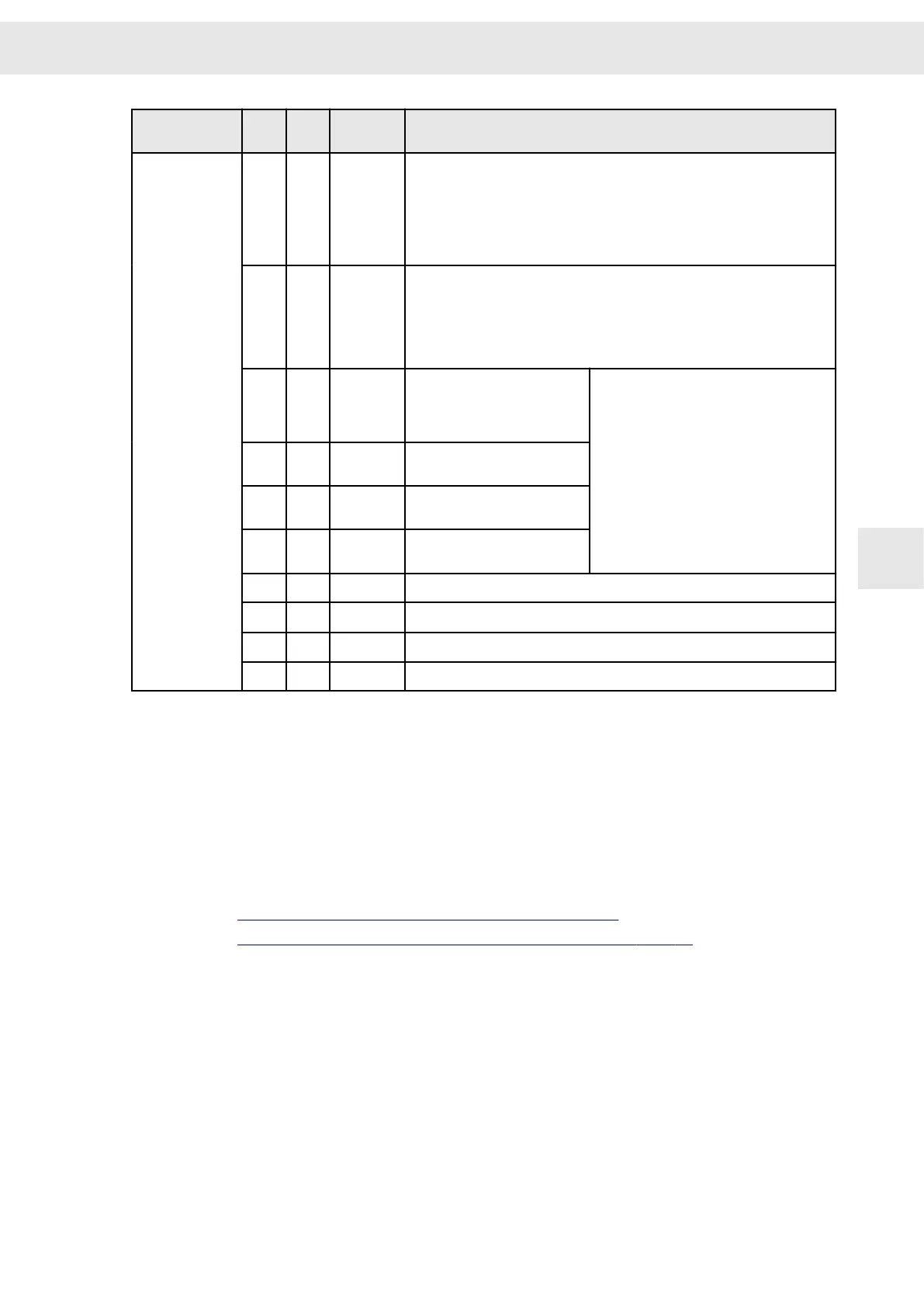
Pin I/O Name Configurable functions
▶ Operation enabled with error reset
▶ Error reset
▶ External hardware OK
▶ Speed direction
▶ MOP up
▶ MOP down
▶ Reducing current limitation / Imax
4 E
IN3
(1)
▶ No function
▶ Pos. limit switch type 1 (speed contr. as p-contr)
▶ Pos. limit switch type 2 (speed contr. as pi-contr)
▶ Parameter set Bit 0
▶ MOP up
▶ MOP down
5 E
IN4
(1)
▶ Enable difference measu‐
ring system
▶ Parameter set Bit 1
▶ Internal target value Bit 3
▶ No function
▶ Speed direction
▶ P-controller
▶ Error reset
▶ External hardware OK
▶ Low gain Kpn
▶ Docking function
▶ Teach no-load current
▶ MOP up
▶ MOP down
▶ Reset commutation
6 E IN5 ▶ Parameter set Bit 2
▶ Internal target value Bit 2
7 E IN6 ▶ Parameter set Bit 3
▶ Internal target value Bit 1
8 E IN7 ▶ Parameter set Bit 4
▶ Internal target value Bit 0
9 E TEMP Motor temperature sensor (against GND)
10 E
AIN0+
(2)
Reference speed value (reference to ground) (pin coded)
11 I/O GND Ground
12 I/O GND Ground
(1)
See also X17.
(2)
In order to use this analog input make the following setting in the software
drivemaster2
: Activate the para‐
meter “Single-ended” for “Analog-In 0”.
Single-ended means that there is no differential signal, i.e. there is no negative signal but the reference
potential ist GND. => more prone to faults (unbalanced)
Specification of terminal connections
▶ Conductor cross-section solid/stranded: 0.14 to 1.5 mm²
▶ Tightening torque: 0.22 to 0.25 Nm
Related topics
Connection example: "X16/17 – Digital Inputs", page 60
Connection example: "Temperature Sensor of the Motor", page 71
W
Connector Pin Assignment
Drive System SD2S - Hardware Description 0362X49xy / 0362129xy 43
7

 Loading...
