Priniples of analog value processing
4.5 Wiring resistance thermometers and resistors
S7-300 Automation System Module data
4-10 Manual, 08/2006, A5E00105505-04
4.5 4.5 Wiring resistance thermometers and resistors
Introduction
This chapter contains a description of wiring resistance thermometers and resistors and
points to which particular attention must be paid.
Signal transducers for measuring resistance which can be wired
● With 4-wire connection
● With 3-wire connection
● With 2-wire connection
Wiring resistance thermometers and resistors
During a resistance measurement, the module supplies a constant current through terminals
I
C+
and I
C-
. The constant current is fed to the resistor to be measured and then measured as
voltage drop. It is imperative to wire the constant current cables directly to the resistance
thermometer/resistor.
Measurements with programmed 4-or 3-wire connection parameters compensate for line
resistance and therefore deliver considerably better accuracy than that gained from the
mesurement with a 2-wire connection.
Measurements with a programmed 2-wire connection also record the line resistance in
addition to their own resistance.
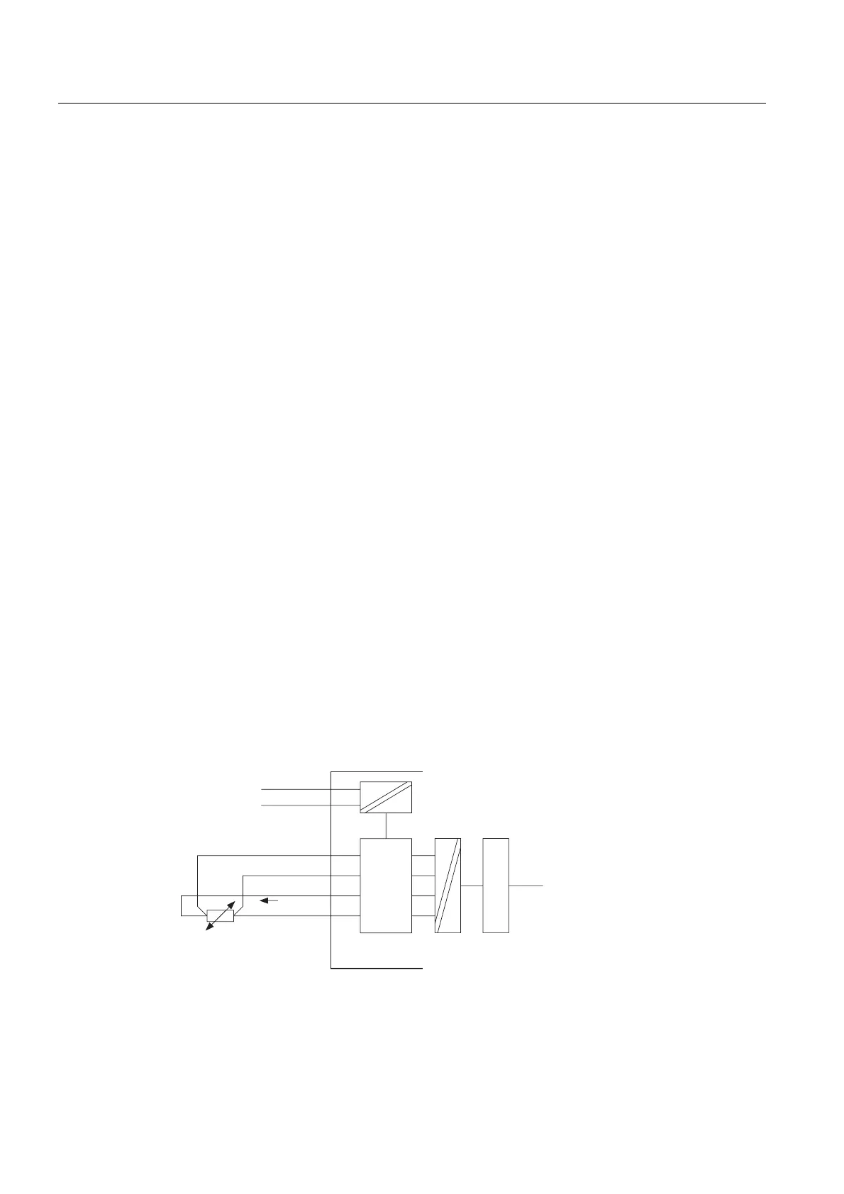
4-wire connection of a resistance thermometer
The voltage generated at the resistance thermometer is measured via the M
+
and M
-
terminals. Watch out for the polarity when you wire the cable (wire (I
C+
and M
+
, and I
C -
and
M- at the resistance thermometer.)
Always wire the I
C
+, M+, I
C
- and M- cables directly to the resistance thermometer.
0
0ದ
/
0
,&
0$1$
,&ದ
,&
/RJLF
$'&
%DFNSODQH
EXV
Figure 4-9 4-wire connection of resistance thermometers to an electrically isolated analog input
 Loading...


