Digital modules
3.5 How to protect digital modules from inductive overvoltages
S7-300 Automation System Module data
3-10 Manual, 08/2006, A5E00105505-04
3.5 3.5 How to protect digital modules from inductive overvoltages
Inductive overvoltages
Overvoltages occur when inductive reactance is deactivated. Examples of this are relay coils
and contactors.
Integrated overvoltage protection
The digital output modules of S7-300 have integrated overvoltage protection equipment.
Extra overvoltage protection
Inductive reactances should only be configured with extra overvoltage protection equipment
in the following instances:
● If SIMATIC output current circuits can be deactivated by extra fitted contacts (e.g. relay
contacts).
● If the inductive reactances are not activated by SIMATIC modules.
Note: Ask the suppliers of inductive reactances what size of overvoltage protection
equipment should be used.
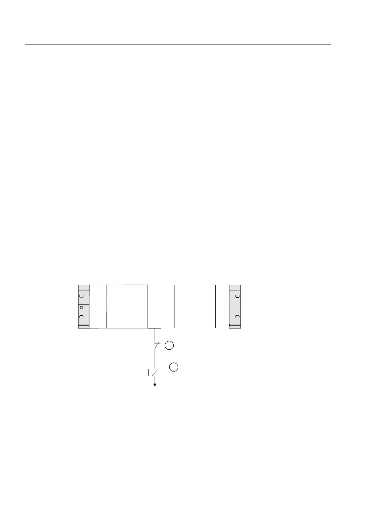
Example
The following diagram shows an output current circuit which make extra overvoltage
protection equipment necessary.
&3836 60 6060 60 60 60
Figure 3-1 Relay contact for emergency stop in output current circuit
① Contact in output current circuit
② Inductive reactance needs a protective circuit
 Loading...


