Parameter sets of signal modules
A.4 Parameters of analog input modules
S7-300 Automation System Module data
A-8 Manual, 08/2006, A5E00105505-04
Noise suppression
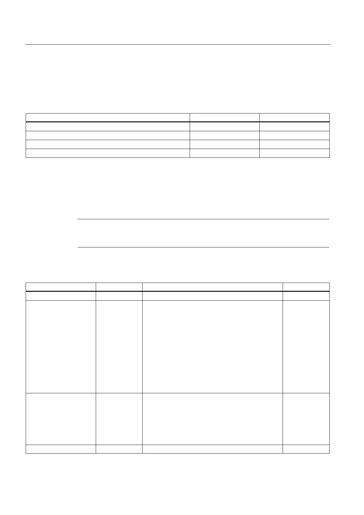
The table below contains the coding at byte 1 of data record 1 for the various frequencies
(see the previous figure.) Make allowances for the resultant integration time at each channel!
Table A-5 Noise suppression codes of analog input modules
Noise suppression Integration time Code
400 Hz 2.5 ms 2#00
60 Hz 16.7 ms 2#01
50 Hz 20 ms 2#10
10 Hz 100 ms 2#11
Measuring methods and ranges
The table below shows all measuring methods and ranges of the analog input module,
including their codes. Enter these codes at bytes 2 to 5 in data record 1 (refer to the previous
figure.)
Note
You may have to reposition a measuring range module of the analog input module to suit the
measuring range.
Table A-6 Measuring range codes of analog input modules
Measuring method Code Measuring range Code
disabled 2#0000 disabled 2#0000
Voltage 2#0001 ± 80 mV
± 250 mV
± 500 mV
± 1 V
± 2.5 V
± 5 V
1 V to 5 V
0 V to 10 V
± 10 V
± 25 mV
± 50 mV
2#0001
2#0010
2#0011
2#0100
2#0101
2#0110
2#0111
2#1000
2#1001
2#1010
2#1011
4-wire transducer 2#0010 ± 3.2 mA
± 10 mA
0 mA to 20 mA
4 mA to 20 mA
± 20 mA
± 5 mA
2#0000
2#0001
2#0010
2#0011
2#0100
2#0101
2-wire transducer 2#0011 4 mA to 20 mA 2#0011
 Loading...


