Analog modules
6.5 Analog input module SM 331; AI 8 x 14 Bit High Speed; synchronous; (6ES7331-7HF0x-0AB0)
S7-300 Automation System Module data
6-36 Manual, 08/2006, A5E00105505-04
The minimum T
i
value you can set in
HW Konfig
is derived from the defined T
WE
value plus
calculation and transfer times required by the IM 153.
The specified T
DPmin
value is determined by the size of the DP slave/IM 153 configuration: Of
the diverse installed modules, the slowest always determines the time T
DPmin
.
Note
When operated in "synchronous" mode, the modules automatically sets "Integration time:
none/interference frequency", irrespective of parameter settings in
STEP 7
. none /
interference frequency". "Hardware interrupt" functionality is not available in "synchronous"
mode.
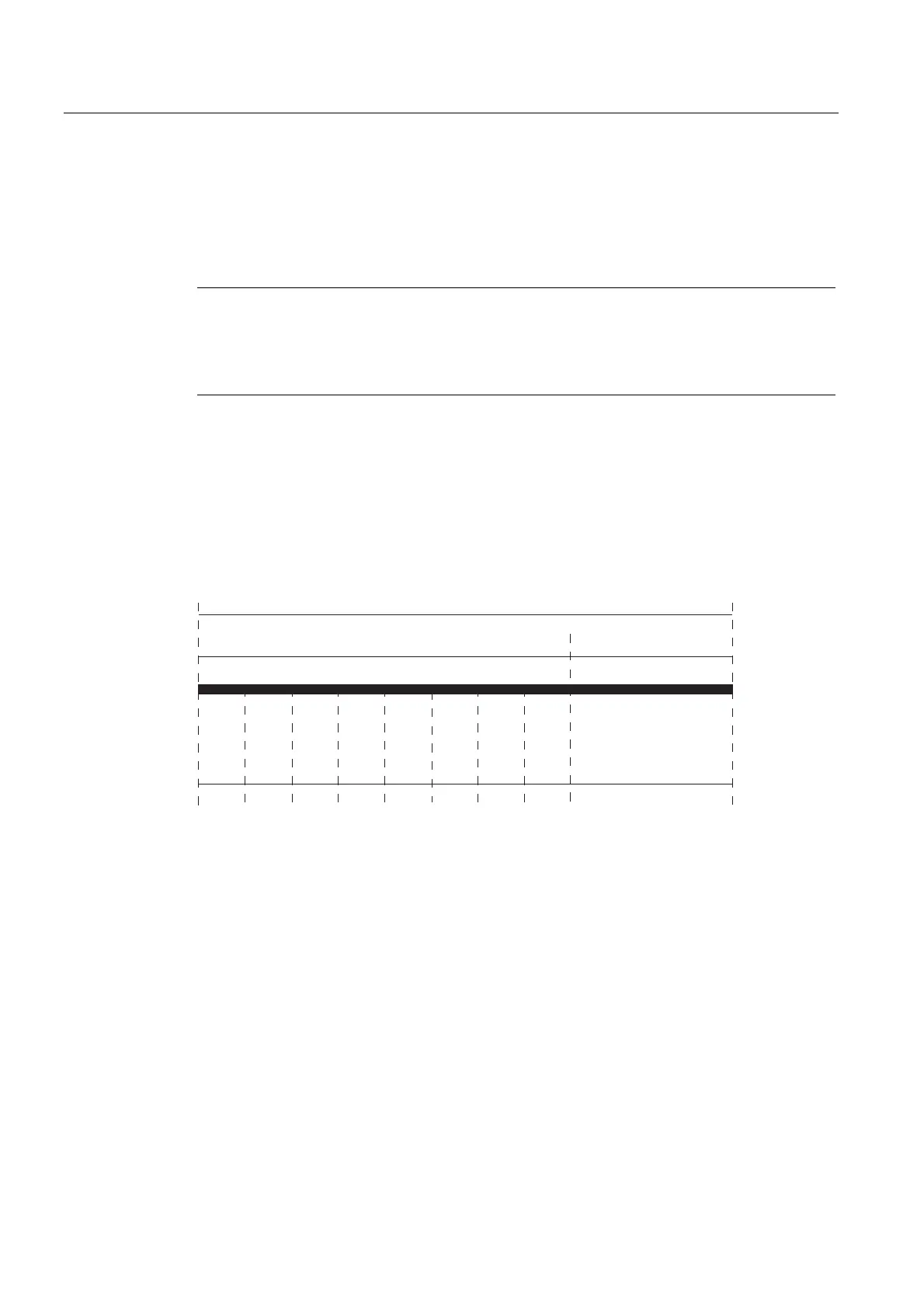
Calculation of filter and processing times
The same time conditions always apply, regardless of the number of configured channels.
The time relative to the clock signal for reading a specific channel is calculated according to
the formula:
T
WE
_CH = (channel number +1) x 52 µs + tv; tv = 119 to 209 µs
wV wV wV wV wV wV wV wV
&+ &+ &+ &+ &+ &+ &+ &+
wV
7:(
$'FRQYHUVLRQ LQWHUQDOSURFHVVLQJWY
Figure 6-9 Calculation of filter and processing times
Definition of isochronous mode
The module starts with the analog-to-digital conversion of channel 7, and saves the result
internally. Next, it converts channels 6...0 sequentially at intervals of 52 ms and in the same
way. After an additional internal processing time, it outputs the result of all converted
channels to the backplane bus interface where it can be fetched by the CPU.
Further information
For further information on synchronous mode, refer to the
STEP 7,
Online Help, and in the
ET 200M Distributed IO System
and
Synchronicity
manuals.
 Loading...


