Analog modules
6.6 Analog input module SM 331; AI 8 x 13 Bit;(6ES7331-1KF01-0AB0)
S7-300 Automation System Module data
Manual, 08/2006, A5E00105505-04
6-41
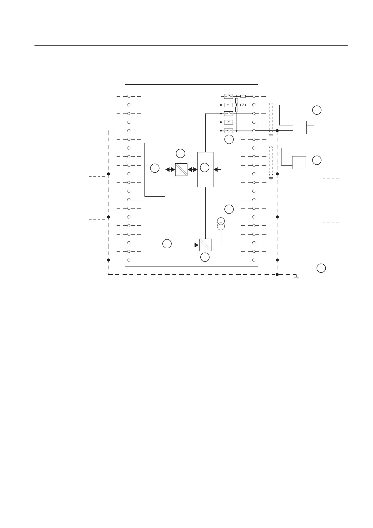
Wiring: 2 and 4-wire measuring transducer for current measurement
/
0
/
0
'08
8
,
6
ದ
0
0
ದ
8
,
6
ದ
0
0
ದ
8
,
6
ದ
0
0
ದ
8
,
6
ದ
0
0
ದ
&+
&+
&+
&+
8
,
6
ದ
0
0
ದ
8
,
6
ದ
0
0
ದ
8
,
6
ದ
0
0
ದ
8
,
6
ದ
0
0
ದ
&+
&+
&+
&+
'08
Figure 6-12 Block diagram and wiring diagram
① 4-wire transducer (0/4...20 mA or ± 20 mA)
② 2-wire transducer (4...20 mA)
③ Potential compensation
④ Internal supply
⑤ + 5V from backplane bus
⑥ Logic and backplane bus interface
⑦ Electrical isolation
⑧ Multiplexer
⑨ Analog to Digital Converter (ADC)
⑩ Source of current
 Loading...


