Home
Siemens
Controller
6ES7 305-1BA80-0AA0
Siemens 6ES7 305-1BA80-0AA0 User Manual
4
of 1
of 1 rating
594 pages
Give review
Manual
Specs
To Next Page
To Next Page
To Previous Page
To Previous Page
Loading...
Dimensional dra
wings
C.3 Dimensional drawing
s of the interface modules
S7-300 Automation System Module data
C-12
Manual, 08/2006, A5E00105505-04
IM 365
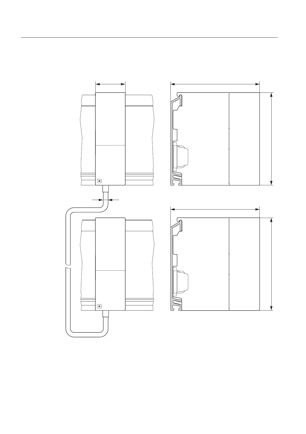
The figure below shows the dimensi
onal drawing of interface mod
ule IM 365.
Figure C-17
Interface module IM 365
481
483
Table of Contents
Default Chapter
3
Manual, 08/2006
3
Table of Contents
7
1 General Technical Data
19
Standards and Certifications
19
Electromagnetic Compatibility
23
Shipping and Storage Conditions for Modules and Backup Batteries
25
Mechanical and Ambient Climatic Conditions for S7-300 Operation
26
Information on Insulation Tests, Protection Class, Degree of Protection and Rated Voltage of the S7-300
28
Rated Voltages of the S7-300
28
SIPLUS S7-300 Modules
29
Mechanical and Climatic Environmental Operating Conditions for SIPLUS S7-300 Modules
31
Table 1-2 SIPLUS S7-300 Modules
31
2 Power Supply Modules
33
Power Supply Module PS 305; 2 A; (6AG1305-1BA80-0AA0)
33
Table 2-1 Reaction of the PS 305;(2 A) Power Supply Module to Atypical Operating Conditions
35
Power Supply Module PS 307; 2 A; (6ES7307-1BA00-0AA0)
36
Table 2-2 Reaction of the PS 307; 2A Power Supply Module to Atypical Operating Conditions
38
PS 307; 5 a Power Supply Module; (6ES7307-1Eax0-0AA0)
40
Table 2-3 Reaction of the PS 307; 5A Power Supply Module to Atypical Operating Conditions
42
PS 307; 10 a Power Supply Module; (6ES7307-1KA00-0AA0)
45
Table 2-4 Reaction of the PS 307; 10A Power Supply Module to Atypical Operating Conditions
46
3 Digital Modules
49
Evaluating Diagnostic Data of Signal Modules in the User Program
49
Module Overview
50
Table 3-1 Digital Input Modules
50
Table 3-2 Digital Input Modules: Overview of Properties (Continued)
51
Table 3-3 Digital Output Modules
52
Table 3-5 Relay Output Modules
53
Table 3-6 Digital IO Modules
54
Steps in Selecting and Commissioning the Digital Module
55
Programming Digital Modules
56
Diagnostics of Digital Modules
57
How to Protect Digital Modules from Inductive Overvoltages
58
Digital Input Module SM 321; DI 32 X DC 24 V; (6ES7321-1BL00-0AA0)
60
Digital Output Module SM 321; DI 32 X AC 120 V; (6ES7321-1EL00-0AA0)
62
Digital Input Module SM 321; DI 16 X DC 24 V; (6ES7321-1BL02-0AA0)
65
Digital Input Module SM 321; DI 16 X DC 24 V High Speed; (6ES7321-1BH10-0AA0)
67
Digital Input Module SM 321; DI 16 X 24 VDC; with Hardware and Diagnostic Interrupts (6ES7321-7BH01-0AB0)
69
Isochronous Mode
73
Parameters of SM 321; DI 16 X DC 24 V
75
Table 3-9 Assigning Interrupt Parameters to the Inputs of SM 321; DI 16 X DC 24 V
76
Diagnostics of SM 321; DI 16 X DC 24 V
77
Reactions of SM 321; DI 16 X DC 24 V
78
Table 3-12 Diagnostic Messages of the SM 321; DI 16 X DC 24 V, Causes of Error and Troubleshooting
78
Interrupts of SM 321; DI 16 X DC 24 V
79
Digital Input Module SM 321; DI 16 X DC 24 V; Source Reading; (6ES7321-1BH50-0AA0)
82
Digital Input Module SM 321; DI 16 X 24/48 VUC (6ES7321-1CH00-0AA0)
84
Digital Input Module SM 321; DI 16 X 48-125 VDC; (6ES7321-1CH20-0AA0)
86
Digital Input Module SM 321; DI 16 X 120/230 VAC (6ES7321-1FH00-0AA0)
88
Digital Input Module SM 321; DI 8 X 120/230 VAC (6ES7321-1FH01-0AA0)
90
Digital Input Module SM 321; DI 8 X 120/230 VAC ISOL (6ES7321-1FF10-0AA0)
93
Digital Output Module SM 322; DO 32 X 24 VDC/ 0.5 A; (6ES7322-1BL00-0AA0)
95
Digital Output Module SM 322; DO 32 X 120/230 VAC/1 A; (6ES7322-1FL00-0AA0)
98
Digital Output Module SM 322; DO 16 X 24 VDC/ 0.5 A; (6ES7322-1BL01-0AA0)
102
Digital Output Module SM 322; DO 16 X DC 24 V/ 0.5 a High Speed; (6ES7322-1BL01-0AA0)
105
Digital Output Module SM 322; DO 16 X UC 24/48 V; (6ES7322-5GH00-0AB0)
108
Parameters of the Digital Output Module SM 322 DO 16 X UC24/48 V
111
Table 3-16 Structure of the Data Record for SM 322 DO 16 X UC 24/48 V
112
Digital Output Module SM 322; DO 16 X AC 120/230 V/1 A; (6ES7322-1FH00-0AA0)
114
Digital Output Module SM 322; DO 8 X DC 24 V/ 2 A; (6ES7322-1BF01-0AA0)
117
Digital Output Module SM 322; DO 8 X DC 24 V/ 0.5 A; with Diagnostics Interrupt; (6ES7322-8BF00-0AB0)
120
Parameters of SM 322; DO 8 X DC 24 V/0.5 a
125
Diagnostics of SM 322; DO 8 X DC 24 V/0.5 a
126
Table 3-20 Diagnostic Messages of SM 322; DO 8 X DC 24 V/0.5 A, Causes of Error and Troubleshooting
127
Reaction of SM 322; DO 8 X DC 24 V/0.5 a
128
Table 3-21 Influence of the CPU Operating State and of the Supply Voltage L+ of SM 322; DO 8 24 VDC/0.5 a on Output Values
128
Interrupts of SM 322; DO 8 X DC 24 V/0.5 a
129
Digital Output Module SM 322; DO 8 X DC 48-125 V/1.5 A; (6ES7322-1CF00-0AA0)
130
Digital Output Module SM 322; DO 8 X AC 120/230 V/2 A; (6ES7322-1FF01-0AA0)
133
Digital Output Module SM 322; DO 8 X AC 120/230 V/2 a ISOL (6ES7322-5FF00-0AB0)
136
Parameters of SM 322; DO 8 X AC 120/230 V/2 a ISOL
139
Diagnostics of SM 322; DO 8 X AC 120/230 V/2 a ISOL
140
Interrupts of SM 322; DO 8 X AC 120/230 V/2 a ISOL
140
Relay Output Module SM 322; DO 16 X Rel. AC 120/230 V; (6ES7322-1HH01-0AA0)
141
Relay Output Module SM 322; DO 8 X Rel. AC 230 V; (6ES7322-1HF01-0AA0)
145
Relay Output Module SM 322; DO 8 X Rel. AC 230V/5A; (6ES7322-5HF00-0AB0)
149
Parameters of SM 322; DO 8 X Rel. AC 230V/5A
154
Diagnostics of SM 322; DO 8 X Rel. AC 230V/5A
154
Interrupts of SM 322; DO 8 X Rel. AC 230V/5A
155
Relay Output Module SM 322; DO 8 X Rel. AC 230 V/5 A; (6ES7322-1HF10-0AA0)
155
Digital IO Module SM 323; DI 16/DO 16 X DC 24 V/0.5 A; (6ES7323-1BL00-0AA0)
160
Digital IO Module SM 323; DI 8/DO 8 X DC 24 V/0.5 A; (6ES7323-1BL01-0AA0)
164
Digital IO Module SM 327; DI 8/DO 8 X DC 24 V/0.5 A; Programmable (6ES7327-1BH00-0AB0)
168
Parameters of SM 327; DI 8/DX 8 X DC 24 V/0.5 a
172
Structure of Data Record 1 of SM 327; DI 8/DO 8 X DC 24 V/0.5 a
173
4 Priniples of Analog Value Processing
175
Overview
175
Wiring Transducers to Analog Inputs
175
Wiring Electrically Isolated Transducers
177
Wiring Electrically Non-Isolated Transducers
179
Connecting Voltage Transducers
181
Connecting Current Transducers
182
Wiring Resistance Thermometers and Resistors
184
Wiring Thermocouples
186
Table 4-1 Options of Compensating the Reference Junction Temperature
188
Connecting Thermocouples with Internal Compensation
189
Connecting Thermocouples with External Compensation
190
Table 4-2 Ordering Data of the Reference Junction
192
Connecting Loads/Actuators to Analog Outputs
194
Connecting Loads/Actuators to Voltage Outputs
195
Connecting Loads/Actuators to Current Outputs
197
5 Representation of the Analog Values of Analog Modules
199
Representation of the Analog Values of Analog Input Channels
200
Table 5-3 Bipolar Input Ranges
201
Table 5-5 Representation of Analog Values in the ±1 V to ±10 V Voltage Measuring Range
202
Table 5-7 Representation of Analog Values in the 1 V to 5 V and 0 V to 10 V Voltage Measuring Ranges
203
Table 5-9 Representation of Analog Values in the 0 Ma to 20 Ma and 4 Ma to 20 Ma Current Measuring Ranges
204
Table 5-11 Presentation of Analog Values for Resistance Thermometers PT 100, 200, 500,1000 and PT 10, 50,100, 500 GOST (0.003850) Standard
205
Table 5-13 Presentation of Analog Values for Resistance Thermometers Pt 100, 200, 500,1000 und Pt 10, 50, 100, 500 GOST (0.003850) Klima
206
Table 5-15 Representation of the Analog Values of ni 100, 120, 200, 500, 1000 and LG-Ni 1000 Resistance Thermometers
207
Table 5-17 Representation of the Analog Values of ni 100 GOST Klima Resistance Thermometers
208
Table 5-19 Representation of the Analog Values of Cu 10 Resistance Thermometers
209
Table 5-21 Representation of the Analog Values of Cu 10, 50, 100, 500 GOST Standard Resistance Thermometers
210
Table 5-23 Representation of the Analog Values of Thermocouples Type C
211
Table 5-25 Representation of the Analog Values of Thermocouples Type J
212
Table 5-27 Representation of the Analog Values of Thermocouples Type L
213
Table 5-29 Representation of the Analog Values of Thermocouples Type R, S
214
Table 5-31 Representation of the Analog Values of Thermocouples Type U
215
Representation of the Analog Values of Analog Output Channels
216
Table 5-35 Representation of Analog Values in the ±10 V Output Range
217
Table 5-37 Representation of Analog Values in the ±20 Ma Output Range
218
Setting the Measuring Method and Ranges of Analog Input Channels
219
Reactions of the Analog Modules
221
Influence of the Supply Voltage and Operating Mode
221
Table 5-39 Dependencies of the Analog IO Values on the Cpu's Operating State and on the L Supply Voltage
222
Influence of the Range of Analog Values
223
Influence of Operational Limits and Basic Error Limits
224
Conversion and Cycle Times of Analog Modules
225
Settling and Response Times of Analog Output Channels
228
Programming Analog Modules
229
Parameters of Analog Input Modules
229
Diagnostics Functions of Analog Modules
230
Diagnostic Messages of Analog Input Modules
231
Diagnostics Messages of Analog Output Modules
231
Causes of Error and Troubleshooting at Analog Input Modules
232
Causes of Error and Troubleshooting at Analog Output Modules
232
Interrupts of Analog Modules
233
6 Analog Modules
235
Steps from the Selection of Analog Modules to Commissioning
236
Module Overview
237
Analog Input Modules
237
Table 6-2 Analog Input Modules: Overview of Properties (Continued)
238
Analog Output Modules
240
Analog IO Modules
241
Analog Input Module SM 331; AI 8 X 16 Bit; (6ES7331-7NF00-0AB0)
242
Measuring Methods and Ranges
247
Adjustable Parameters
247
Additional Information on SM 331; AI 8 X 16 Bit
249
Analog Input Module SM 331; AI 8 X 16 Bit; (6ES7331-7NF10-0AB0)
251
Measuring Methods and Ranges
256
Adjustable Parameters
257
Additional Information to SM 331; AI 8 X 16 Bit
258
Analog Input Module SM 331; AI 8 X 14 Bit High Speed; Synchronous; (6ES7331-7Hf0X-0AB0)
262
Measuring Methods and Ranges
267
Adjustable Parameters
268
Isochronous Mode
269
Additional Information on SM 331; AI 8 X 14 Bit High Speed, Isochronous
271
Analog Input Module SM 331; AI 8 X 13 Bit;(6ES7331-1KF01-0AB0)
272
Measuring Methods and Ranges
280
Adjustable Parameters
281
Additional Information to SM 331; AI 8 X 13 Bit
282
Analog Input Module SM 331; AI 8 X 12 Bit;(6ES7331-7KF02-0AB0)
282
Measuring Methods and Ranges
291
Adjustable Parameters
293
Additional Information to SM 331; AI 8 X 12 Bit
294
Analog Input Module SM 331; AI 2 X 12 Bit; (6ES7331-7KB02-0AB0)
295
Measuring Methods and Ranges
303
Adjustable Parameters
305
Additional Information to SM 331; AI 2 X 12 Bit
306
Analog Input Module SM 331; AI 8 X RTD; (6ES7331-7PF01-0AB0)
307
Measuring Methods and Ranges
313
Einstellbare Parameter
314
Additional Information to SM 331; AI 8 X 16 RTD
316
Analog Input Module SM 331; AI 8 X TC; (6ES7331-7PF11-0AB0)
320
Measuring Methods and Ranges
328
Adjustable Parameters
329
Additional Information on SM 331; AI 8 X TC
330
Table 6-31 Content of the 4 Bytes of Additional OB40 Information During Hardware or End of Cycle Interrupts
333
Analog Output Module SM 332; AO 8 X 12 Bit; (6ES7332-5HF00-0AB0)
334
Output Ranges SM 332; AO 8 X 12 Bit
339
Adjustable Parameters
339
Additional Information to SM 332; AO 8 X 12 Bit
340
Analog Output Module SM 332; AO 4 X 16 Bit; Isochronous; (6ES7332-7ND02-0AB0)
341
Output Ranges SM 332; AO 4 X 16 Bit
346
Adjustable Parameters
347
Isochronous Mode
348
Additional Information to SM 332; AO 4 X 16 Bit
349
Analog Output Module SM 332; AO 4 X 12 Bit; (6ES7332-5HD01-0AB0)
350
Output Ranges SM 332; AO 4 X 12 Bit
355
Adjustable Parameters
355
Additional Information to SM 332; AO 4 X 12 Bit
356
Analog Output Module SM 332; AO 2 X 12 Bit; (6ES7332-5HB01-0AB0)
357
Output Ranges SM 332; AO 2 X 12 Bit
362
Adjustable Parameters
362
Additional Information to SM 332; AO 2 X 12 Bit
363
Analog IO Module SM 334; AI 4/AO 2 X 8/8 Bit; (6ES7334-0CE01-0AA0)
364
Operating Principle of SM 334; AI 4/AO 2 X 8/8 Bit
370
Measuring Method/Output Type of SM 334; AI 4/AO 2 X 8/8 Bit
371
Measuring and Output Ranges of SM 334; AI 4/ AO 2 X 8/8 Bit
371
Additional Information to SM 334; AI 4/AO2 X 8/8 Bit
372
Analog IO Module SM 334; AI 4/AO 2 X 12 Bit; (6ES7334-0KE00-0AB0)
372
Adjustable Parameters
377
Measuring Methods and Ranges
378
Additional Information to SM 334; AI 4/ AO 2 X 12 Bit
379
7 Other Signal Modules
381
Module Overview
381
Simulator Module SM 374; IN/OUT 16; (6ES7374-2XH01-0AA0)
382
Dummy Module DM 370; (6ES7370-0AA01-0AA0)
384
Table 7-2 Meaning of the Switch Settings of Dummy Module DM 370
386
Position Decoder Module SM 338; POS-INPUT; (6ES7338-4BC01-0AB0)
387
Isochronous Mode
391
Functions of SM 338; POS-INPUT; Encoder Value Acquisition
392
Gray Code/Binary Code Converter
392
Transferred Encoder Value and Scaling
393
Freeze Function
394
SM 338; POS-INPUT Programming
395
SM 338; POS-INPUT Addressing
396
Diagnostics of SM 338; POS-INPUT
399
Table 7-6 Diagnostics Messages of SM 338, Causes of Error and Troubleshooting
400
Interrupts of SM 338; POS-INPUT
401
8 Interface Modules
403
Module Overview
403
Interface Module IM 360; (6ES7360-3AA01-0AA0)
404
Interface Module IM 361; (6ES7361-3CA01-0AA0)
406
Interface Module IM 365; (6ES7365-0BA01-0AA0)
408
9 RS 485 Repeater
413
Fields of Application and Properties; (6ES7972-0AA01-0XA0)
414
Design of the RS 485 Repeater; (6ES7972-0AA01-0XA0)
415
RS 485 Repeater in Ungrounded and Grounded Operation
416
Technical Data
418
Parameter Sets of Signal Modules
421
Principles of Programming Signal Modules in the User Program
421
A.2 Parameters of Digital Input Modules
422
A.2 Parameters of Digital Input Modules
423
Parameters of Digital Output Modules
424
A.4 Parameters of Analog Input Modules
426
A.4 Parameters of Analog Input Modules
427
Table A-5 Noise Suppression Codes of Analog Input Modules
428
Parameters of Analog Input Module SM 331; AI 8 X RTD
430
Table A-8 Operating Mode Codes of SM 331; AI 8 X RTD
435
Table A-10 Measuring Range Codes of SM 331; AI 8 X RTD
436
Table A-11 Temperature Coefficient Codes of SM 331; AI 8 X RTD
437
Table A-12 Smoothing Codes of SM 331; AI 8 X RTD
438
Parameters of Analog Input Module SM 331; AI 8 X TC
439
Table A-14 Operating Mode Codes of SM 331; AI 8 X TC
443
Table A-15 Noise Suppression Codes of SM 331; AI 8 X TC
444
Table A-17 Codes of the Reaction to Open Thermocouple of SM 331; AI 8 X TC
445
Parameters of Analog Input Module SM 331; AI 8 X 13 Bit
446
Table A-19 Temperature Measurement Codes of the Analog Input Module
447
Table A-21 Measuring Ranges Codes of the Analog Input Module
448
A.8 Parameters of Analog Input Module SM 331; AI 8 X 16 Bit
449
A.8 Parameters of Analog Input Module SM 331; AI 8 X 16 Bit
450
Table A-24 Operating Mode Codes of SM 331; AI 8 X 16 Bit
454
Table A-26 Measuring Range Codes of SM 331; AI 8 X 16 Bit
455
Parameters of Analog Output Modules
456
Parameters of Analog Output Module SM 332; AO 8 X 12 Bit
458
Parameters of Analog IO Modules
460
Table A-33 Measuring Range Codes of Analog IO Modules
462
B.1 Evaluating Diagnostic Data of Signal Modules in the User Program
463
B.2 Structure and Content of Diagnostics Data Bytes 0 to 7
464
Diagnostics Data of Signal Modules
465
Structure and Content of Diagnostics Data Bytes 0
465
Channel-Specific Diagnostics Data, Starting at Byte 8
467
Diagnostics Data of SM 338; POS-INPUT
469
Dimensional Drawings
472
Dimensional Drawings of the Mounting Rails
472
Bus Modules
477
Dimensional Drawings of the Power Supply Modules
478
Dimensional Drawings of the Interface Modules
481
Dimensional Drawings of the Signal Modules
483
Dimensional Drawings of Accessories
484
Table D-1 Accessories and Spare Parts
487
Spare Parts and Accessories for S7-300 Modules
488
Directive on Handling Electrostatic-Sensitive Devices (ESD
489
Definition of ESD
489
Electrostatic Charging of the Body
490
Basic Protective Measures against Electrostatic Discharge
491
Support & Service
493
List of Abbreviations
495
List of Abbreviations
496
Glossary
497
Index
518
Other manuals for Siemens 6ES7 305-1BA80-0AA0
Reference Manual
574 pages
Hardware And Installation Manual
242 pages
Technical Data
244 pages
Technical Data Manual
252 pages
Product Information
208 pages
Quick Start
82 pages
Operating Instructions
5 pages
Function Manual
332 pages
Equipment Manual
79 pages
Installation And Hardware Manual
20 pages
Getting Started
100 pages
4
Based on 1 rating
Ask a question
Give review
Questions and Answers:
Need help?
Do you have a question about the Siemens 6ES7 305-1BA80-0AA0 and is the answer not in the manual?
Ask a question
Siemens 6ES7 305-1BA80-0AA0 Specifications
General
Brand
Siemens
Model
6ES7 305-1BA80-0AA0
Category
Controller
Language
English
Related product manuals
Siemens 6ES7 331-7SF00-0AB0
112 pages
Siemens 6ED1 052-1HB00-0BA2
236 pages
Siemens 6ED1 052-2MD00-0BA2
236 pages
Siemens 6ED1 052-1MD00-0BA2
236 pages
Siemens 6ED1 052-1CC00-0BA2
236 pages
Siemens 6ED1 053-1FB00-0BA2
236 pages
Siemens 6ED1 053-1FH00-0BA2
236 pages
Siemens 6MD86
1256 pages
Siemens RWF55.6
93 pages
Siemens LFL1.635
25 pages
Siemens QAA78.610
221 pages
Siemens SIMODRIVE 611 universal
930 pages
 Loading...


