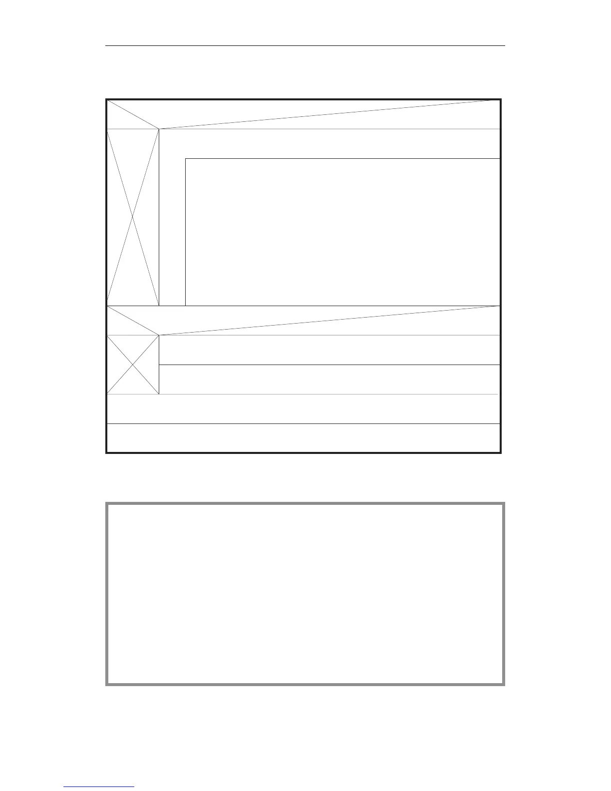
Flow chart for completing the
DX 0 screen forms
Example
NO
YES
Repeat the following procedure until you have made all the necessary
changes in the form:
Position the cursor on the parameter field. The display field F3
at the bottom of the screen indicates whether or not you can select
from different alternatives (SELECT displayed) or change the
parameter value (INPUT displayed).
Are there parameters to be changed in the 2nd screen form?
Are there parameters to be changed in the 1st screen form?
NO YES
Press F6 (CONTINUE); the second screen form is displayed.
Change parameters as explained above for screen 1.
Now press the enter key. The PG software accepts all the parameter
settings from the two screens and generates data block DX 0.
DX0isstoredonthePG.YoucanloaditonthePLCwiththePG’s
TRANSFER function.
- Select the input field:
- SELECT:
Press F3 until the alternative you require is displayed.
- INPUT:
Press F3 once; the cursor jumps to the start
of the field. You can now overwrite the field
with a permissible numerical value.
You want to assign parameters in DX 0 to achieve the following system
program response (different from the defaults):
- mode "interrupts at operation boundaries",
- no timer updating,
- cycle monitoring time = 2.5 seconds,
- level priority for timed interrupts = 2
- system interrupt INT E with priority = 1 .
Continued on the next page
Examples of Parameter Assignment
CPU 948 Programming Guide
7 - 16 C79000-G8576-C848-04