Overview
1.11 Areas in the RFID tag system
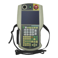
Wireless Teach Pendant F IWLAN V2
Operating Instructions, 08/2010, A5E02453837-01
27
The following figure shows an example configuration of a plant control system which is
operated with a Wireless Teach Pendant F IWLAN.
6DIHW\UHODWHGGHYLFHV
6,0$7,&6)31'3
352),1(7,2FRQWUROOHU
6WDQGDUG+RVW3/&
352),1(7,2FRQWUROOHU
(7b6VWDWLRQ
ZLWK
,031
,2
352),1(7
,2GHYLFH
:LUHOHVV7HDFK3HQGDQW
),:/$1
352),1(7,2GHYLFH
352),1(7
6&$/$1&(:
$FFHVV3R
LQW
6,0$7,&6)
1.11 Areas in the RFID tag system
The following areas are available in a plant for fail-safe operation with RFID tag logon:
● WLAN for communication between a fail-safe controller and HMI device
● Effective range of the RFID tag for logging onto a machine
● RFID transmission and reception range of an HMI device for logging onto a machine
WLAN/iWLAN
Fail-safe controller and HMI device communicate over the radio cell of the access point. The
access point serves as a gateway between the wireless and wired network.
The WLAN or iWLAN in the plant is provided by at least one access point.
The figure below shows an example of the various areas.