Issue 07/04 3 Functions
MICROMASTER 420 Operating Instructions
6SE6400-5AA00-0BP0
103
If the motorized potentiometer is to be used as setpoint source, then either
parameter P1000 or P0719 should be modified or the BICO parameter r1050
should be connected to the main setpoint P1070 or supplementary setpoint P1075.
Contrary to parameter P0719, when parameter P1000 is modified, this implicitly
changes BICO parameters P1070, P1075.
Example: Setpoint via the motorized potentiometer (MOP)
a) Standard method
→ P1000 = 1
b) BICO method → P1070 = 1050
P1075 = 0
The MOP is configured using the following parameters and has the mode of
operation as shown in Table 3-16:
Limits using the minimum frequency P1080 or maximum frequency P1082
Ramp-up/ramp-down time P1120 or P1121
Inhibits MOP reversing function P1032
Saves the MOP setpoint P1031
MOP setpoint P1040
Table 3-16 Mode of operation of the MOP
Motorized potentiometer
Lower Raise
Function
0 0 Setpoint is frozen
0 1 Raise setpoint
1 0 Lower setpoint
1 1 Setpoint is frozen
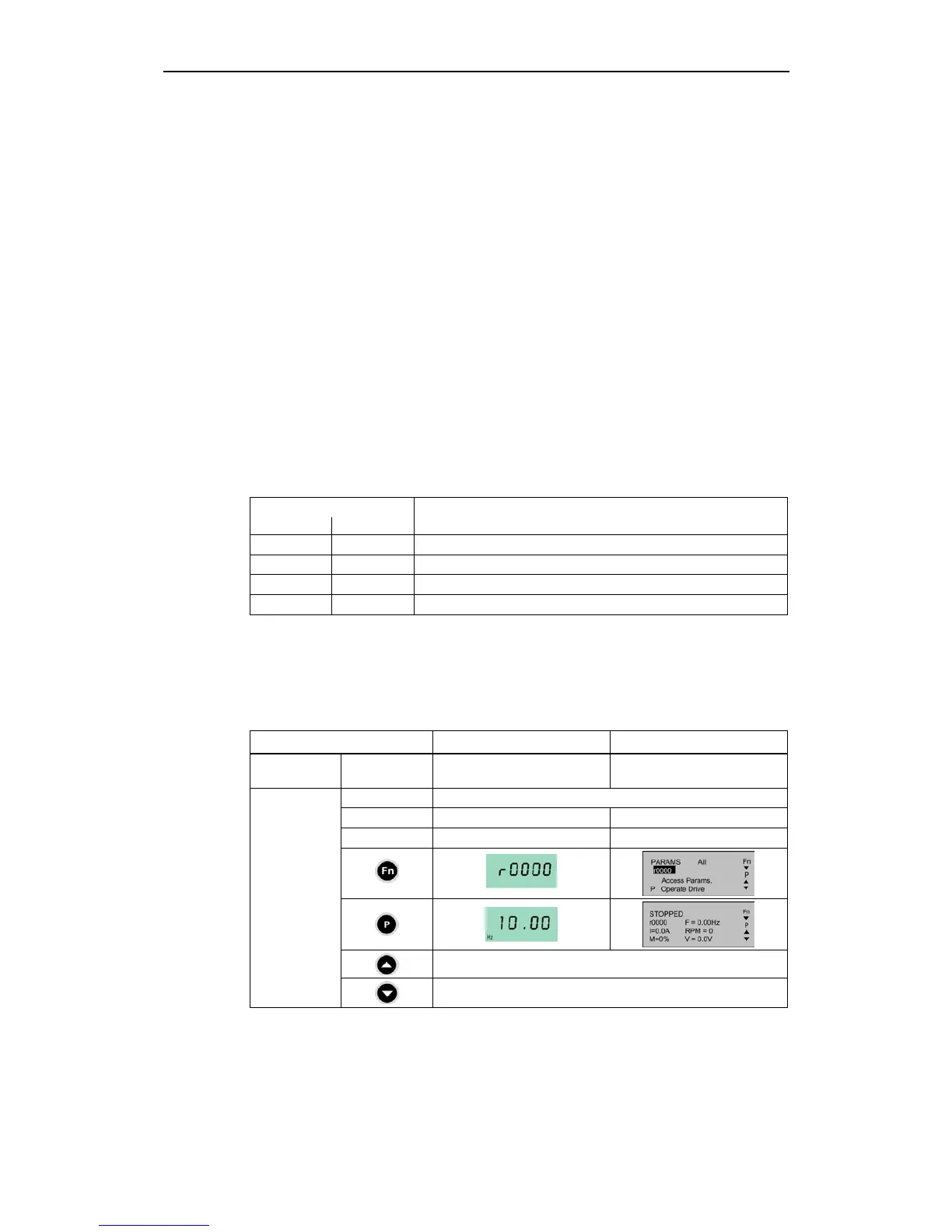
Selecting via BOP or AOP
The following settings / operator actions should be made when selecting the
motorized potentiometer using the BOP or AOP:
Table 3-17 Selecting the motorized potentiometer
Parameters / keys BOP AOP (at the BOP link)
Command
source
P0700 1 4
P1000 1
P1035 - 2032.13 (2032.D)
P1036 - 2032.14 (2032.E)
Raise MOP output frequency
Setpoint
source
Lower MOP output frequency

 Loading...


