Issue 07/04 3 Functions
MICROMASTER 420 Operating Instructions
6SE6400-5AA00-0BP0
125
3.14.2 Compound braking
Parameter range: P1236
Warnings -
Faults -
Function chart number: -
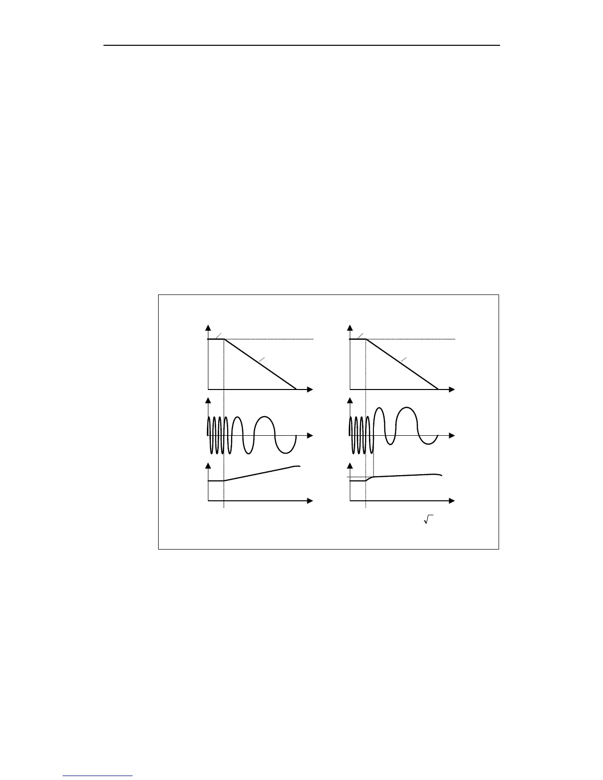
For compound braking (this is enabled using P1236) DC braking is superimposed
with regenerative braking (where the drive regenerates into the line supply as it
brakes along a ramp). If the DC link voltage exceeds the compound switch-in
threshold V
DC-Comp
(refer to Fig. 3-53), then a DC current is impressed as a function
of P1236. In this case, braking is possible with a controlled motor frequency and
minimum regenerative feedback. Effective braking is obtained without having to
use additional components by optimizing the ramp-down time (P1121 for OFF1 or
when braking from f
1
to f
2
, P1135 for OFF3) and using compound braking P1236.
Compound braking is suitable for:
Horizontal motion (e.g. traversing drives, conveyor belts)
Vertical motion (e.g. hoisting gear)
f
i
t
t
f_act
f_set
P1236 = 0
Without Compound braking
u
t
f
i
t
t
f_act
f_set
P1236 >0
With Compound braking
t
DC-link
u
DC-link
U
DC-Comp
P0210213.1U : 0 = P1254
Comp-DC
⋅⋅=
1242r0.98 U : 0 P1254
Comp-DC
⋅=≠
Fig. 3-53 Compound braking
The compound braking switch-in threshold V
DC-Comp
is calculated as a function of
parameter P1254 (Auto detect V
DC
switch-on levels) either directly using the line
supply voltage P0210 or indirectly using the DC link voltage and r1242 (refer to the
formula in Fig. 3-53).

 Loading...


