3 Functions Issue 07/04
MICROMASTER 420 Operating Instructions
72 6SE6400-5AA00-0BP0
3.5.5 Commissioning the application
After the motor – drive inverter combination was commissioned using the quick or
series commissioning, in the following step parameters should be adapted and set
according to the technological requirements. As an example, the following points
should be considered:
Functional requirements of the drive inverter (e.g. process control with PID
controller)
Limit values
Dynamic requirements
Starting torques
Load surge requirement
Overload
Diagnostics
If the application includes a function, which is not covered by the quick or series
commissioning, then the following sections of the function description or the
parameter list should be considered.
Adapting the drive inverter to the application
The parameters designated with * offer more setting possibilities than are listed
here. Refer to the parameter list for additional setting possibilities.
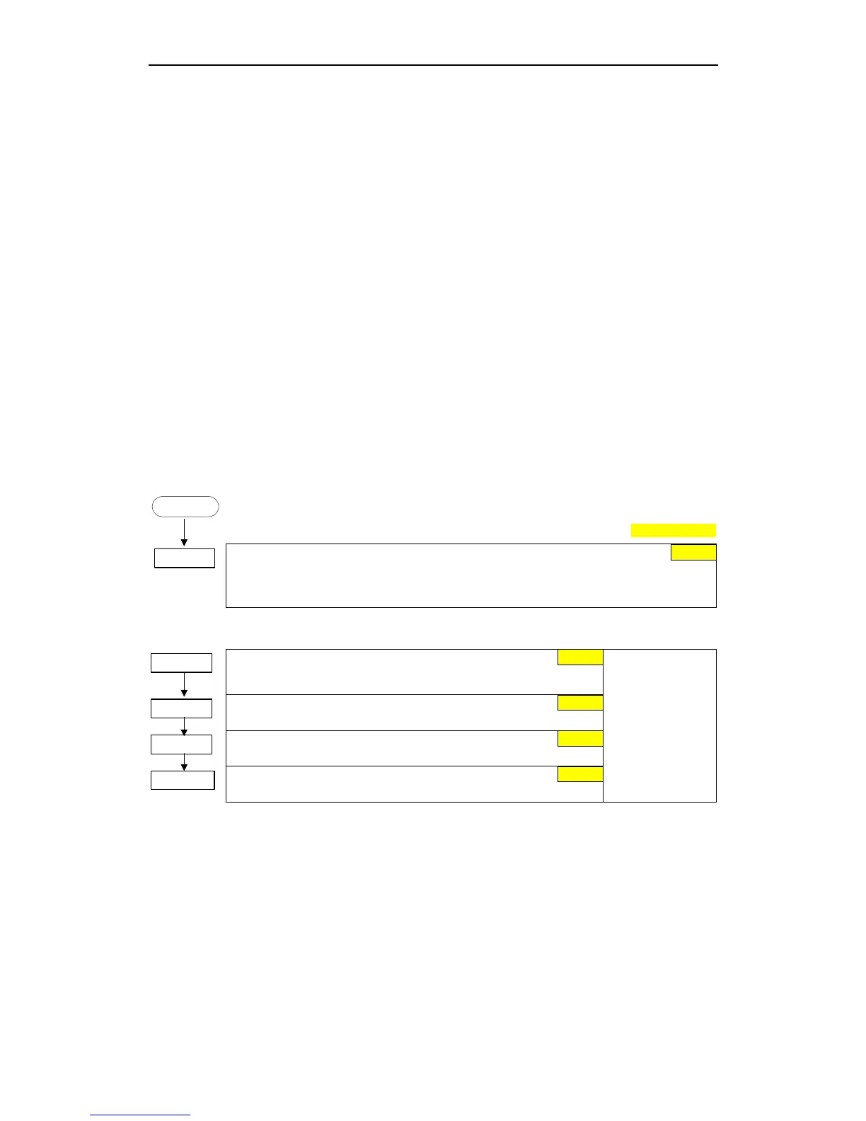
START
Factory settin
P0003 = 3
User access level *
1 Standard (Allows access into most frequently used parameters)
2 Extended (Allows extended access e.g. to inverter I/O functions)
3 Expert (for expert use only)
3.5.5.1 Serial Interface (USS)
P2010 =...
USS baud rate
Sets baud rate for USS communication.
P2011 =...
USS address
Sets unique address for inverter.
P2012 =...
USS PZD length
Defines the number of 16-bit words in PZD part of USS telegram.
P2013 =...
USS PKW length
Defines the number of 16-bit words in PKW part of USS telegram.
Possible
Settings:
3 1200 baud
4 2400 baud
5 4800 baud
6 9600 baud
7 19200 baud
8 38400 baud
9 57600 baud
1
6
0
2
127

 Loading...


