Issue 07/04 3 Functions
MICROMASTER 420 Operating Instructions
6SE6400-5AA00-0BP0
95
3.7 Communications
Parameter range: P2009 – r2091
Function chart number:
CB at COM link FP2700, FP2710
USS at COM link FP2600, FP2610
USS at BOP link FP2500, FP2510
MICROMASTER 420 has 2 serial communication interfaces which can be
simultaneously used. These interfaces are designated as follows in the following
text:
BOP link
COM link
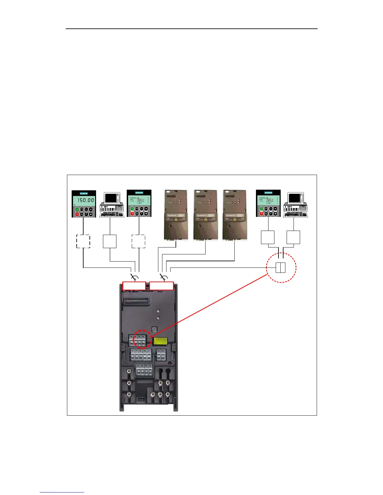
Different units, such as the BOP and AOP operator panels, PCs with the start-up
software DriveMonitor and STARTER, interface modules for PROFIBUS DP,
DeviceNet and CAN as well as programmable controls with communication
processors can be connected at this interface (refer to Fig. 3-21).
1) Option: BOP/AOP door mounting kit
for single inverter control
BOP USS
RS232
USS
RS232
BOP
DriveMonitor/
STARTER
AOP
CB
BOP link
PROFIBUS
board
DeviceNet
board
CAN
board
COM link
CB CB
USS
RS485
AOP
USS
RS485
DriveMonitor/
STARTER
14
15
1) 1)
3)*
1) Option: Operator panel door mounting kit
for single inverter control
2)*
2) Option: PC to inverter connection kit
3) Option: AOP door mounting kit
for multiple inverter control (USS)
4)*
4) Option: RS232-RS485 Converter
Fig. 3-29 Serial communication interfaces - BOP link and COM link

 Loading...


