Issue 07/04 2 Installation
MICROMASTER 420 Operating Instructions
6SE6400-5AA00-0BP0
25
2.3 Mechanical installation
WARNING
♦ To ensure the safe operation of the equipment, it must be installed and
commissioned by qualified personnel in full compliance with the warnings laid
down in these operating instructions.
♦ Take particular note of the general and regional installation and safety
regulations regarding work on dangerous voltage installations (e.g. EN
50178), as well as the relevant regulations regarding the correct use of tools
and personal protective gear.
♦ The mains input, DC and motor terminals, can carry dangerous voltages even
if the inverter is inoperative; wait 5 minutes to allow the unit to discharge after
switching off before carrying out any installation work.
♦ The inverters can be mounted adjacent to each other. If they are mounted on
top of each other, however, a clearance of 100 mm has to be observed.
4
160 mm
6.30"
55 mm
2.2"
Ø 4.5 mm
0.17"
Ø 4.8 mm
0.19"
174 mm
6.85"
138 mm
5.43"
Ø 5.5 mm
0.22"
204 mm
8.03"
174 mm
6.85"
Frame Size A Frame Size B
Frame Size C
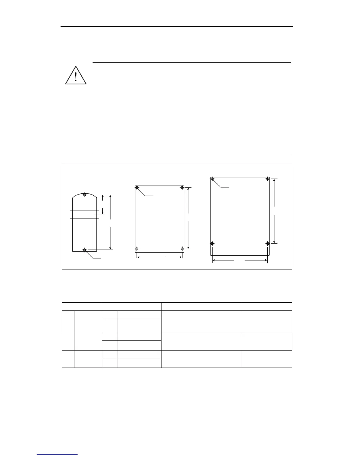
Fig. 2-4 Drill pattern for MICROMASTER 420
Table 2-1 Dimensions and Torques of MICROMASTER 420
Frame-Size Overall Dimensions Fixing Method Tightening Torque
mm 73 x 173 x 149
A
Width x
Height x
Depth
inch 2.87 x 6.81 x 5.87
2 x M4 Bolts
2 x M4 Nuts
2 x M4 Washers for mounting on
standard rail
2.5 Nm
with washers fitted
mm 149 x 202 x 172
B
Width x
Height x
Depth
inch 5.87 x 7.95 x 6.77
4 x M4 Bolts
4 x M4 Nuts
4 x M4 Washers
2.5 Nm
with washers fitted
mm 185 x 245 x 195
C
Width x
Height x
Depth
inch 7.28 x 9.65 x 7.68
4 x M5 Bolts
4 x M5 Nuts
4 x M5 Washers
2.5 Nm
with washers fitted

 Loading...


