3 Functions Issue 07/04
MICROMASTER 420 Operating Instructions
98 6SE6400-5AA00-0BP0
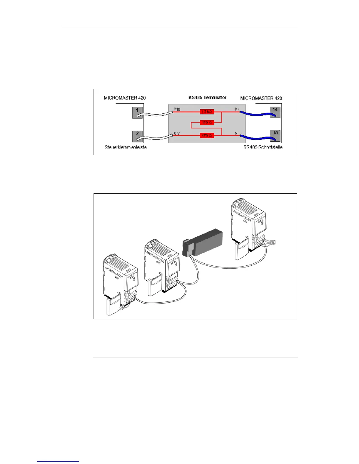
3.7.1 USS bus configuration via COM link (RS485)
Using MICROMASTER with RS485 communication requires a proper termination
at
both ends of the bus (between P+ and N-), and correct pull up/ pull down
resistors at least one end of the bus (e.g. from P+ to P10, and N- to 0 V). (refer to
Fig. 3-30)
Fig. 3-30 RS485 Terminator
When the MICROMASTER drive inverter is the last slave on the bus (refer to Fig.
3-31), and there are no other pull up/pull down resistors on the bus, the supplied
terminator must be connected shown in Fig. 3-30).
First Slave
Last Slave
RS485 Terminator
RS485
Terminator
RS485 Bus
Master
e.g. PLC
Fig. 3-31 USS bus configuration
When the MICROMASTER is the first slave on the bus (refer to Fig. 3-31) the
RS485 Terminator may be used to terminate the bus by using P+ and N- only, for
the bus is powered by the last drive as explained.
NOTE
The supply for the pull up/ pull down resistors must be available whenever RS485
communication is in progress!

 Loading...


