Issue 07/04 2 Installation
MICROMASTER 420 Operating Instructions
6SE6400-5AA00-0BP0
31
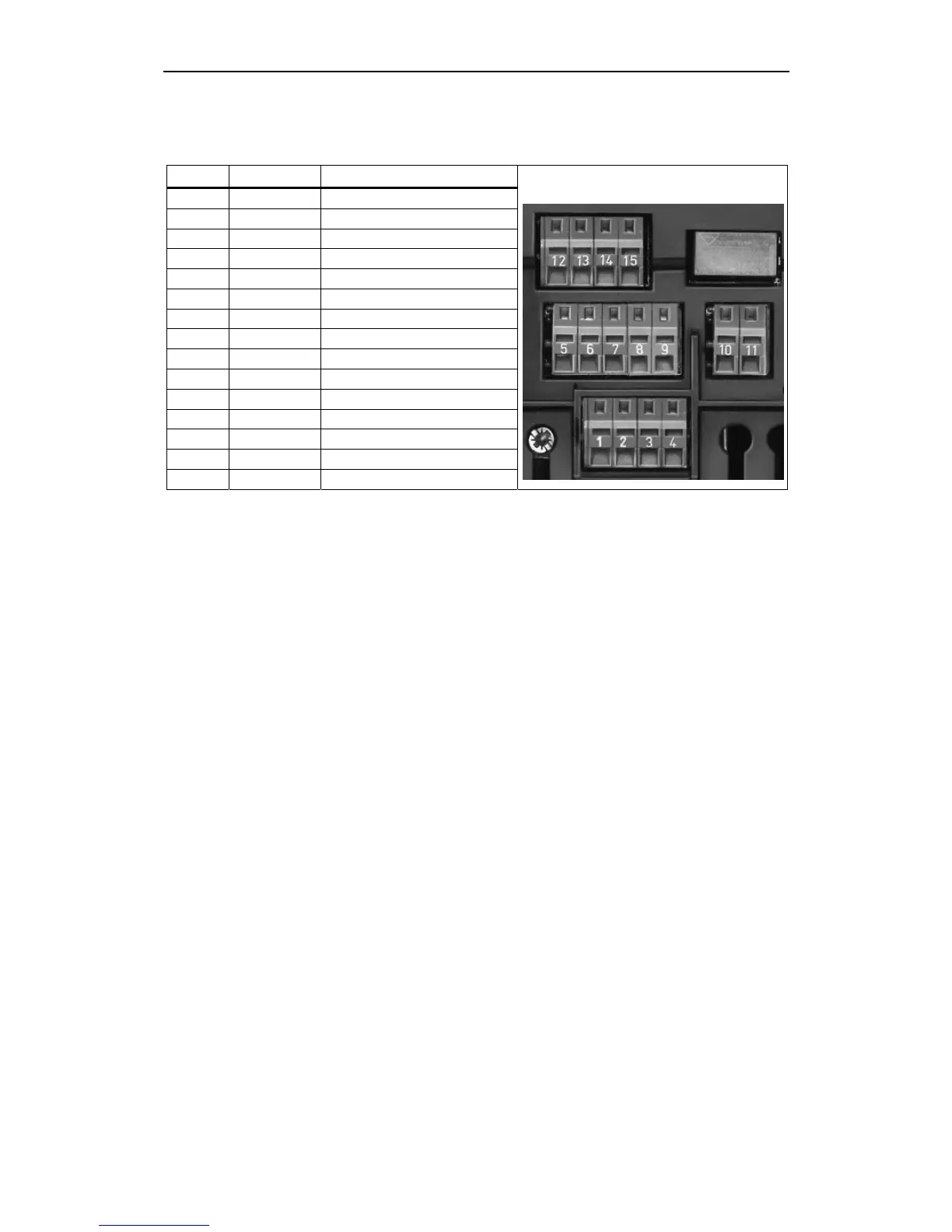
2.4.3 Control terminals
Terminal Designation Function
1 - Output +10 V
2 - Output 0 V
3 ADC+ Analog input 1 (+)
4 ADC- Analog input 1 (-)
5 DIN1 Digital input 1
6 DIN2 Digital input 2
7 DIN3 Digital input 3
8 - Isolated output +24 V / max. 100 mA
9 - Isolated output 0 V / max. 100 mA
10 RL1-B Digital output / NO contact
11 RL1-C Digital output / Changeover contact
12 DAC+ Analog output (+)
13 DAC- Analog output (-)
14 P+ RS485 port
15 P- RS485 port
Fig. 2-7 Control terminals of MICROMASTER 420
A detailed description of the inputs and outputs is provided in Section 3.6.

 Loading...


