Issue 07/04 3 Functions
MICROMASTER 420 Operating Instructions
6SE6400-5AA00-0BP0
93
NOTE
When the filter time constant P0753 (ADC-PT1) is increased, this smoothes the
ADC input signal therefore reducing the ripple. When this function is used within a
control loop, this smoothing has a negative impact on the control behavior and
immunity to noise (the dynamic performance deteriorates).
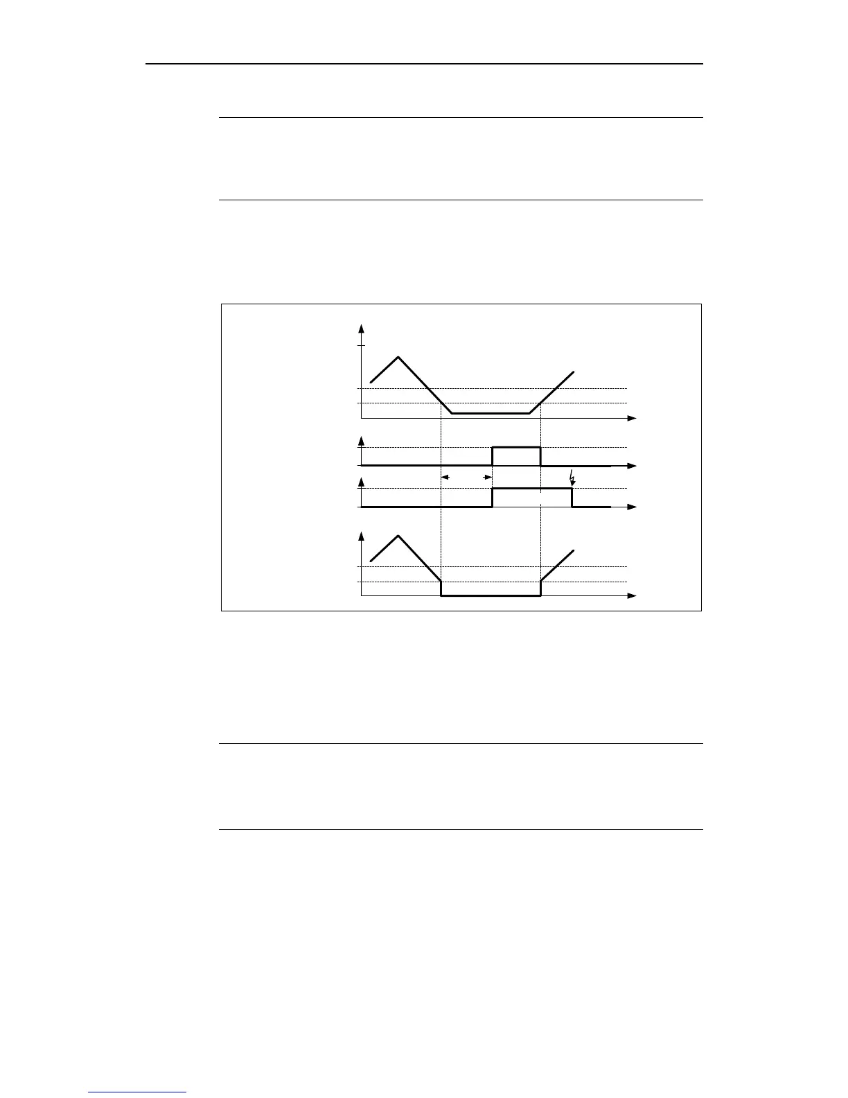
Wire breakage monitoring
The wire breakage monitoring (refer to Fig. 3-25) is set using parameters P0756
and P0761. If the input signal of the analog input falls below the wire breakage
threshold (0.5
*
P0761), then after the time in P0762 expires, fault F0080 is output
and the status bit is set in parameter r0751.
t0
Signal loss
t0
P0761
V
1
P0761 0,5 ⋅
10
P0762
r0751
t0
1
F0080
Fault acknowl.
Analog input
t0
Act. ADC after scaling
r0755
Fig. 3-26 Wire breakage monitoring
The following secondary conditions/limitations apply to the wire breakage
monitoring:
The monitoring function must be activated using parameter P0756
Width of the ADC dead zone P0761 > 0
Wire breakage monitoring if the ADC input quantity ≤ 0.5
*
P0761
Note
The wire-breakage monitoring function is only possible for unipolar analog
inputs.
Input range 0 to 0.5
*
P0761 of the analog input must be excluded when
activating the wire breakage monitoring for normal operation.

 Loading...


