Issue 07/04 3 Functions
MICROMASTER 420 Operating Instructions
6SE6400-5AA00-0BP0
49
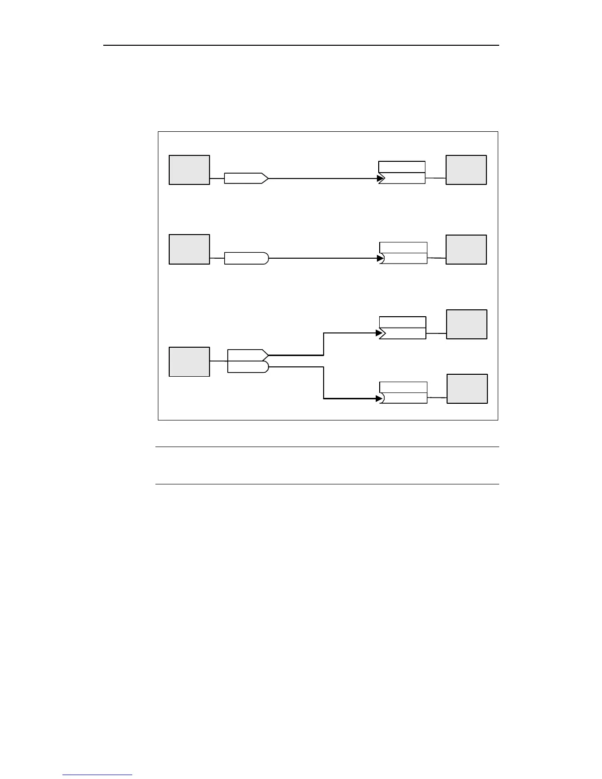
In order to interconnect two signals, a BICO setting parameter (signal receiver)
must be assigned the required BICO monitoring parameter (signal source). A
typical BICO interconnection is shown using the following examples (refer to Fig.
3-6).
Connector output (CO) ===> Connector input (CI)
CO/BO: Act. status word 1
FB
r0755
P1070 = 755
(755)
P1070
FB
P0840 = 751.0
r0751
(751:0)
P0840
FB
(751:0)
P0840
(751:0)
P0840
P0731 = 52.3
P2051 = 52
P0731
FB
P0731
(52:3)
P0731
FB
P2051
(52)
FB
r0052
r0052
Binector output (BO) ===> Binector input (BI)
Connector output / Binector output (CO/BO)
BO: Status word of ADC
CO: Act. ADC after scal. [4000h]
CI: Main setpoint
BI: ON/OFF1
CI: PZD to CB
BI: Function of digital output 1
Function
Function
Function
Function
Function
Function
Function
Fig. 3-6 BICO connections (examples)
NOTE
BICO parameters with the CO, BO or CO/BO attributes can be used a multiple
number of times.

 Loading...


