3 Functions Issue 07/04
MICROMASTER 420 Operating Instructions
124 6SE6400-5AA00-0BP0
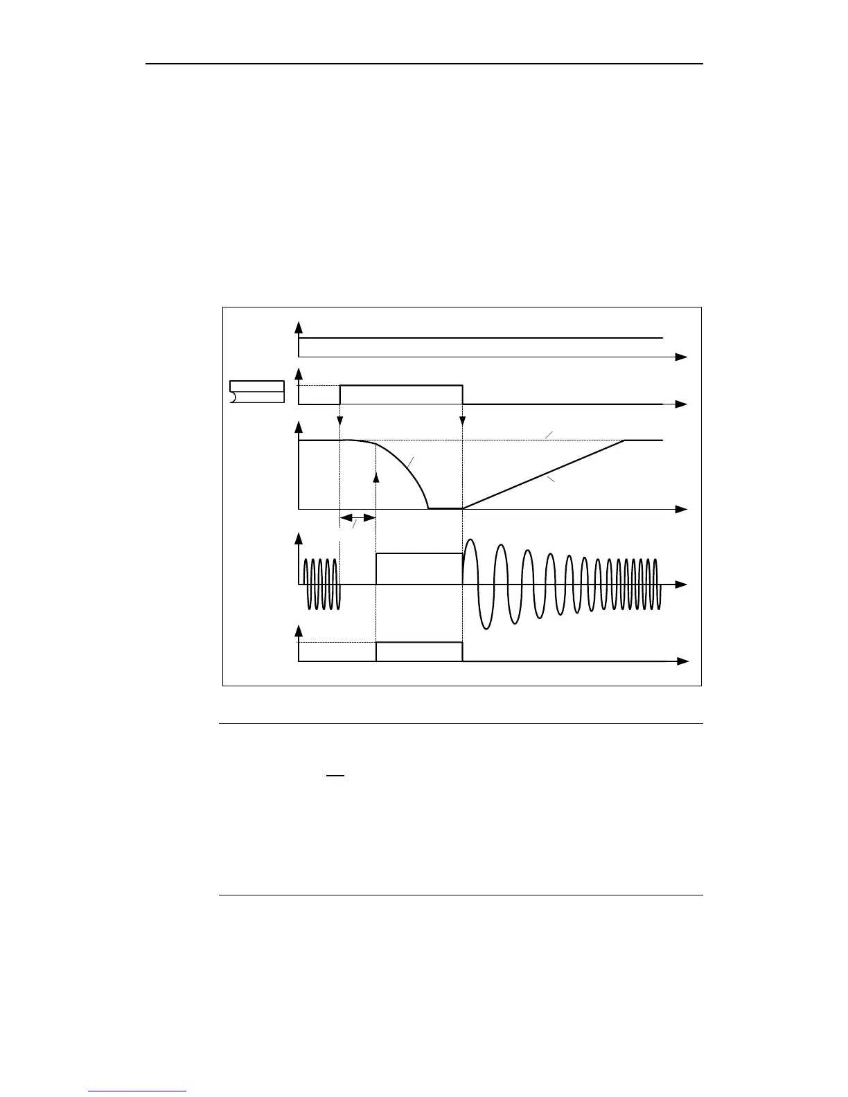
Sequence ➁
1. Enabled and selected using BICO parameter P1230 (refer to Fig. 3-52)
2. The inverter pulses are inhibited for the duration of the de-magnetizing time
P0347.
3. The requested braking current P1232 is impressed for the time selected and
the motor is braked. This state is displayed using signal r0053 bit 00.
4. After DC braking has been cancelled, the drive accelerates back to the setpoint
frequency until the motor speed matches the drive inverter output frequency. If
there is no match, then there is danger that a fault will be output as a result of
overcurrent - F0001. This can be avoided by activating the flying restart
function.
ON/OFF1
f
P0347
f*
i
t
t
t
t
1
0
f_act
DC braking
0
1
DC braking active
r0053
Bit 00
t
f_set
(0:0)
P1230.C
BI: Enable DC brk.
Fig. 3-52 DC braking after external selection
NOTE
1. The "DC braking" function is only practical for induction motors !
2. DC braking is not suitable to hold suspended loads !
3. For DC current braking, the motor kinetic energy is converted into thermal
energy in the motor. If braking lasts too long, then the drive can overheat !
4. While DC braking, there is no other way of influencing the drive speed using an
external control. When parameterizing and setting the drive system, then as far
as possible, it should be tested using real loads !
5. DC braking is independent of the ON command. This means that it can even
be selected in the "Ready" state.

 Loading...


