3 Commissioning
MICROMASTER 430 Operating Instructions
6SE6400-5AC00-0BP0
43
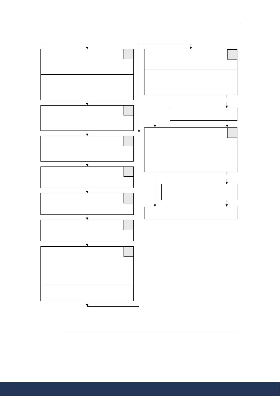
P1000 Selection of Frequency Setpoint
2)
1 Motor potentiometer setpoint
2 Analog setpoint 1
3 Fixed frequency setpoint
7 Analog setpoint 2
P1080 Min. Motor Frequency
Setting range: 0 - 650 Hz
Sets minimum motor frequency (0 - 650 Hz) at which
the motor will run irrespective of the frequency set-
point. The value is valid for both motor directions.
P1082 Max. Motor Frequency
Setting range: 0 - 650 Hz
Sets maximum motor frequency (0 - 650 Hz) at which
the motor will run irrespective of the frequency set-
point. The value is valid for both motor directions.
P1120 Ramp-Up Time
Setting range: 0 - 650 s
Time taken for the motor to accelerate from standstill
up to maximum motor frequency.
P1121 Ramp-Down Time
Setting range: 0 - 650 s
Time taken for motor to decelerate from maximum
motor frequency down to standstill.
P1135 OFF3 ramp-down time
Setting range: 0 - 650 s
Defines the ramp down time from the maximum
frequency to standstill for the OFF3 command.
P1300 Control mode
0 V/f with linear charac.
1 V/f with FCC
2 V/f with parabolic charac.
3 V/f with programmable charac.
5 V/f for textile applications
6 V/f with FCC for textile applications
19 V/f control with independent voltage setpoint
P1910 Select motor data identification:
0 Disabled
1 Identification of all parameters with
parameter change
P3900 End Quick Commissioning
0 End Quick Commissioning without motor
calculation or factory reset.
1 End Quick Commissioning with motor
calculation and factory reset.
2 End Quick Commissioning with motor
calculation and with I/O reset.
3 End Quick Commissioning with motor
calculation but without I/O reset.
1
1
1
1
1
2
1
2
2
Note
For additional settings for setpoint see Parameter
List.
If P1000 = 1 the selection depends on the settings of
P0700 to P0708
Note
Motor identification must be performed with a cold
motor (20 °C). If the ambient temperature is not
within the range of 20°C (+5°C), P0625 Ambient
motor temperature must be updated
Note
Vector control modes can only be used together with
an asynchronous motor
Quick Commissioning complete, the inverter goes
into ready-to-run state
Alarm A0541
Motor data idendification active.
P1910 = 1P1910 = 0
P3900 = 1,2 P3900 = 3
Switch on Motor, Motor data identification
starts. After completing motor identifi-
cation, Alarm message A0541 disappears.
2)
The parameters offer more setting options than listed here. See Parameter List for further setting
options.
www.eltra-trade.com
+421 552 601 099
info@eltra-trade.com