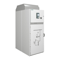
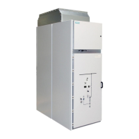
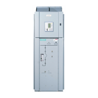
Assembling the panels
110-0084.9 / 15 NXAIR / ≤ 40 kA 71
Bag with connecting elements
Busbar version for switch-disconnector panel for U
r
≤ 17,5 kV
The standard version of the busbar system contains plastic tubes that cover each horizontal bar. Before
assembling the busbars, plastic insulation tubes must insert on each horizontal bar of busbar system.
In the switch-disconnector panel, the busbars of phases L1, L2 and L3 are bolted with the copper spacer to the
feeder bars. Thereby, observe the following instructions as shown below.
Mounting the feeder bars
The connection of the feeder bars is always fixed at the last step to avoid the stress
on the feeder bars.
First, always mount the main busbars from right and left panel, on all
phases L1, L2, L3, and then make the connection of the feeder bars.
Observe the direction of the bolt head side and the bolted joint side of the
busbar connection with feeder bars.
Fig. 82: Assembly of 1250 A busbar, feeder 1250A
Bolt M12x40,
conical spring
washer
Nut, conical
spring washer
Copper spacer
with three holes
Copper spacer
with four holes
Bag with connecting
elements:
110-0770.3

 Loading...


