You can find additional information on this in the section "Differences between multiple station
systems and single station systems (Page 17)".
A description of an example for a small system is available in the section "Combination of
engineering station and operator station on a single PC (Page 21) ".
Example configuration
'RPDLQ
&RQWUROOHU
%$7&+FOLHQWV
26FOLHQWV
06FOLHQWRSW
0(6RIILFHQHWZRUNV
06VHUYHU
(QJLQHHULQJ
VWDWLRQ
06FOLHQW
RSWLRQDO
5HGXQGDQW26
VHUYHUV
5RXWH&RQWURO
VLQJOHVWDWLRQ
V\VWHP
%$7&+
VHUYHU
(QJLQHHULQJ
VWDWLRQ
$XWRPDWLRQV\VWHP
$6
$XWRPDWLRQV\VWHP
$6+
3ODQWEXV,QGXVWULDO(WKHUQHW
7HUPLQDOEXV,QGXVWULDO(WKHUQHW
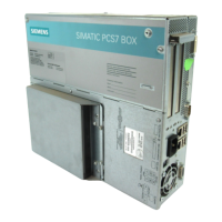
6,0$7,&
3&6%2;
Topology
The terminal bus and system bus can be configured as follows:
● As Industrial Ethernet (10/100/1000 Mbps)
● Bus, tree, ring, star or redundant ring structures
Data communication
● Terminal bus
The following table shows data communication in the PCS 7 plant.
PCS 7 is also connected to components at higher levels, for example MES level and office
networks, via the terminal bus.
PC components of a PCS 7 system
3.9 Connecting PC stations
PCS 7 - PC Configuration (V8.2)
40 Installation Manual, 03/2016, A5E36200050-AB
 Loading...


