Spare parts and accessories
8.2 Optional accessories
Power Module PM240-2
Hardware Installation Manual, 12/2015, A5E33294624B AD
109
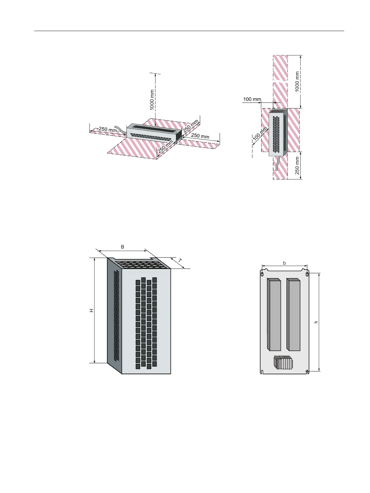
Figure 8-4 Minimum clearances for the braking resistor when mounting on a flat surface and for
wall/panel mounting
Keep shaded areas free of any devices and components.
Dimensions and drilling patterns
Figure 8-5 Braking resistor
 Loading...