Connecting-up
5.1 Line and motor connection
Power Module PM240-2
Hardware Installation Manual, 12/2015, A5E33294624B AD
45
Connection terminals at the inverter
Table 5- 3 Connection type, cable cross sections and tightening torques
Cross-section and tightening torque
Line, motor cable,
DC link and braking
resistor
1.5 ... 2.5 mm
2
0.5 Nm 16 … 14 AWG: 4.5 lbf in 8 mm
Line, motor cable,
DC link and braking
resistor
1.5 ... 6 mm
2
0.6 Nm 16 … 10 AWG: 5.5 lbf in 8 mm
Line, motor cable,
DC link and braking
resistor
6 …16 mm: 1.3 Nm 10 … 6 AWG: 12 lbf in 10 mm
Line, motor cable and
DC link
10 … 35 mm
2
: 2.5 … 4.5 Nm 20 … 10 AWG: 22 lbf in
8 … 2 AWG: 40 lbf in
18 mm
Braking resistor
2.5 … 16 mm
2
: 1.2 … 1.5 Nm 20 … 6 AWG: 15 lbf in 10 mm
Line, motor cable and
DC link
25 … 70 mm
2
: 8 … 10 Nm 6 … 3/0 AWG: 88.5 lbf in
25 mm
Braking resistor
10 … 35 mm
2
: 2.5 … 4.5 Nm 20 … 10 AWG: 22 lbf in
8 … 2 AWG: 40 lbf in
18 mm
Line, motor cable and
DC link with
cable lugs according to
35 … 2*120 mm
2
: 22 … 25 Nm 1 … 2*4/0 AWG: 210 lbf.in --
Braking resistor
25 … 70 mm
2
: 8 … 10 Nm 6 … 3/0 AWG: 88.5 lbf in
25 mm
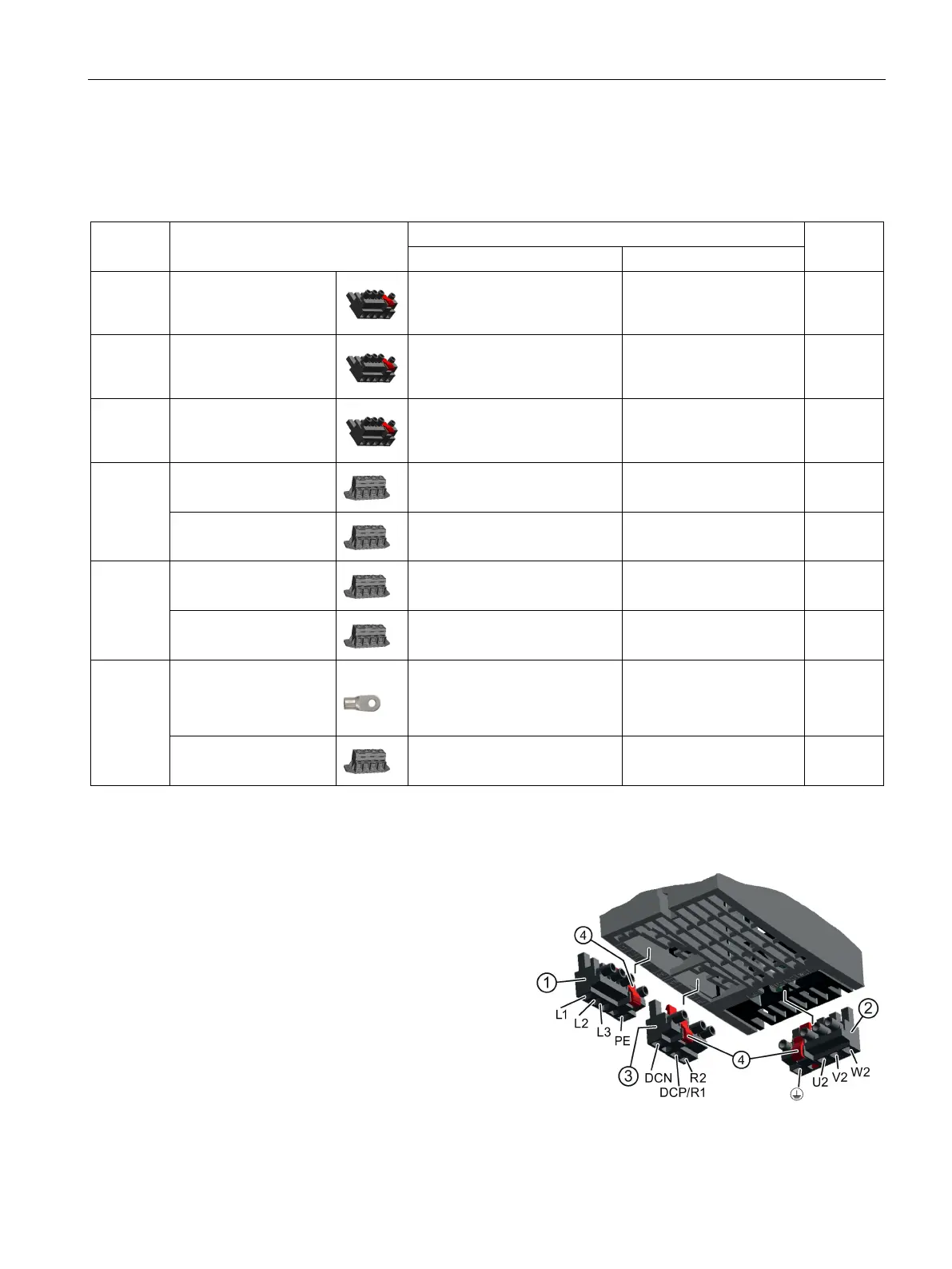
Connecting terminals FSA, FSB, FSC
The Power Modules are equipped with
withdrawable connectors.
You can withdraw the connector by pres
s-
ing the red lever to release the interlock.
The connectors are designed so that they
cannot be accidentally interchanged.
Connection plug for a braking resistor