Technical data
7.3 Technical data, 200 V inverters
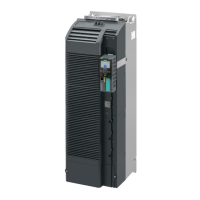
Power Module PM240-2
Hardware Installation Manual, 12/2015, A5E33294624B AD
69
Technical data, 200 V inverters
Motors for 200 V Power Modules
For the 200 V Power Modules, induction motors are permissible in the range from
25 % … 150 % of the inverter power without any restrictions.
Use motors for inverter operation or with higher insulation levels.
General data, 200 V inverters
Line voltage FSA … FSC 200 V … 240 V 1-ph. AC
for LO base load power 0.55 kW … 4 kW
for HO base load power 0.37 kW … 3 kW
200 V … 240 V 3-ph. AC
for LO base load power 0.55 kW … 7.5 kW
for HO base load power 0.37 kW … 5.5 kW
200 V … 240 V 3-ph. AC -20 % / + 10 %
3 AC 0 V … 0.95 x input voltage (max.)
0 … 550 Hz, depending on the control mode
Line impedance FSA … FSC
Uk ≥ 2 %, for lower values, we recommend a line reactor, or a Power Module
with the next higher power rating.
Line reactor not required
Power factor λ FSA … FSC
0.7 without line reactor for Uk ≥ 2 %
0.85 with line reactor for Uk < 2 %
0.95 line reactor not required
< LO base load input current
Overvoltage category acc.
The inverter insulation is designed for surge voltages according to overvoltage Category III.
Pulse frequency 4 kHz (factory setting),
Adjustable as follows in 2 kHz steps:
• 4 kHz … 16 kHz for devices from 0.55 kW … 30 kW.
• 4 kHz … 8 kHz for devices 36 kW and higher
If you increase the pulse frequency, the inverter reduces the maximum output current.
Short-circuit current rating
(SCCR)
FSA … FSC ≤ 100 kA rms
FSD … FSF ≤ 65 kA rms
Branch protection and short-circuit strength according to UL and IEC
(https://support.industry.siemens.com/cs/ww/en/view/109479152)
Electromagnetic compati-
bility according to IEC/EN
Devices with integrated filter are suitable for Category C2 environments.
DC braking, compound braking, dynamic braking with integrated braking chopper
 Loading...