Installing/mounting
4.3 Mounting the Power Modules
Power Module PM240-2
32 Hardware Installation Manual, 12/2015, A5E33294624B AD
Note
Brake relay
If you are using a brake relay to control a motor brake, then mount the brake relay at the rear
of the lower
shield plate before you attach the shield module to the inverter. See also
Mounting and connecting the brake relay
(Page 117)
If you are using an inverter with integrated line filter, then you must mount the shield module
as described below.
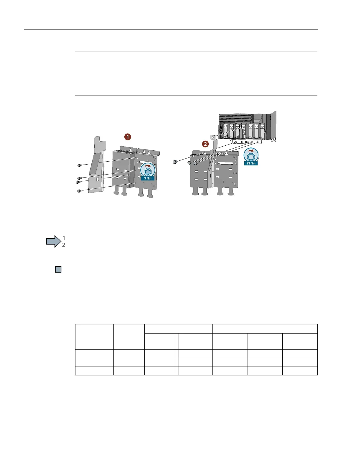
Proceed as follows to mount the shield module:
1. Attach the EMC connecting bracket to the shield plate
①.
2. Screw the shield module to the inverter
② using three screws, as shown in the diagram.
You have correctly mounted the shield module.
Dimension drawings and drilling dimensions for PT Power Modules
Table 4- 3 Mounting dimensions
The Power Modules can be mounted side-by-side. For tolerance reasons, we recommend a lateral
clearance of 1 mm.
2)
Wall thickness of the control cabinet ≤ 3.5 mm