EasyManua.ls Logo

Siemens PM240-2

Siemens PM240-2
132 pages
To Next Page IconTo Next Page
To Previous Page IconTo Previous Page
Loading...
Installing/mounting
4.3 Mounting the Power Modules
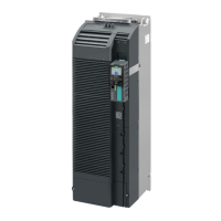
Power Module PM240-2
Hardware Installation Manual, 12/2015, A5E33294624B AD
33
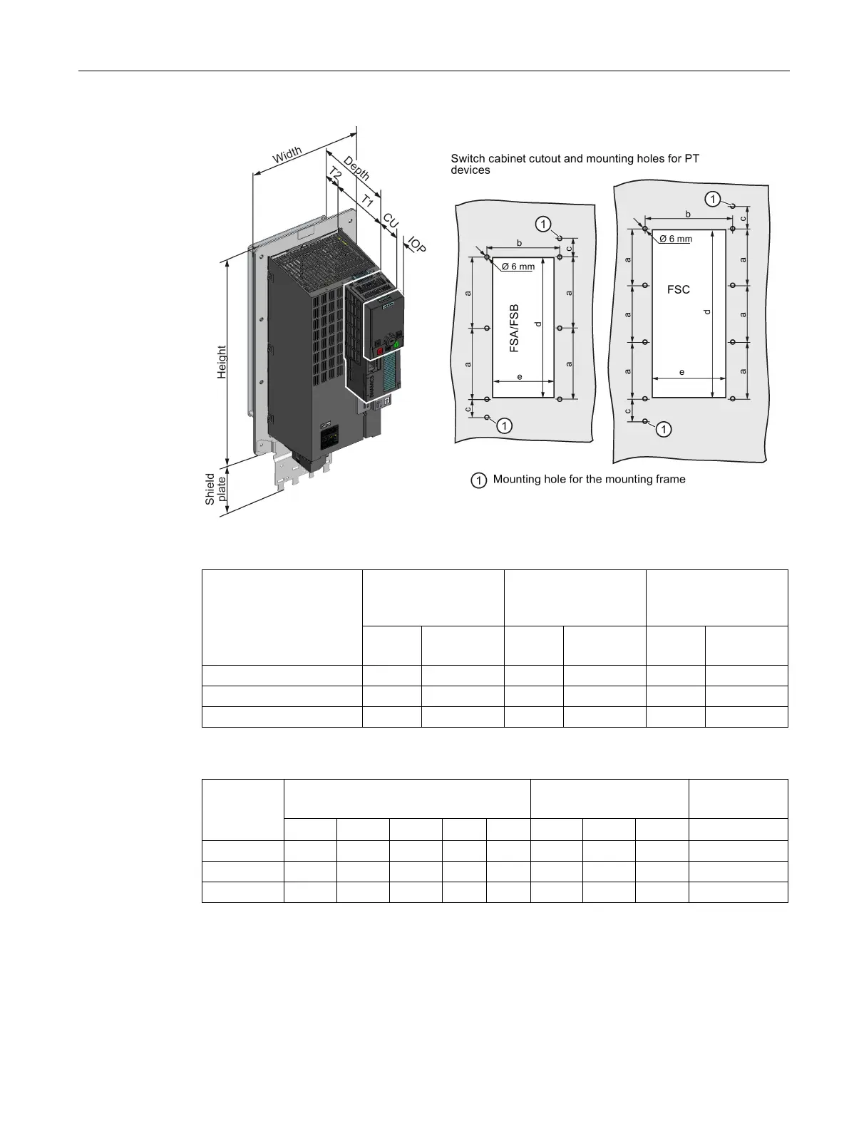
Table 4- 4 Depth with Control Unit and operator panel
Control Unit
Power Module + Con-
trol Unit
(mm)
Power Module + Con-
trol Unit + IOP
(mm)
Power Module + Con-
trol Unit + BOP
(mm)
Total
in the cabi-
net
Total
in the cabi-
net
Total
in the cabi-
net
CU230P-2
231
177.7
253
199.7
244
190.7
CU240B-2 / CU240E-2
212
158.7
234
180.7
225
171.7
CU250S-2
234
180.7
256
202.7
247
193.7
Table 4- 5 Drilling dimensions, cooling clearances and fixing
Frame size
Drilling dimensions and dimensions for
the control cabinet cutout (mm)
Cooling air clearances
(mm)
Fixing
a
b
c
d
e
Top
Bottom
Front
FSA
103
106
27
198
88
80
100
8 x M5 / 3.5
FSB
147.5
134
34.5
304
116
80
100
8 x M5 / 3.5
FSC
123
174
30.5
365
156
80
100
10 x M5 / 3.5

Table of Contents

Related product manuals