Spare parts and accessories
8.2 Optional accessories
Power Module PM240-2
Hardware Installation Manual, 12/2015, A5E33294624B AD
111
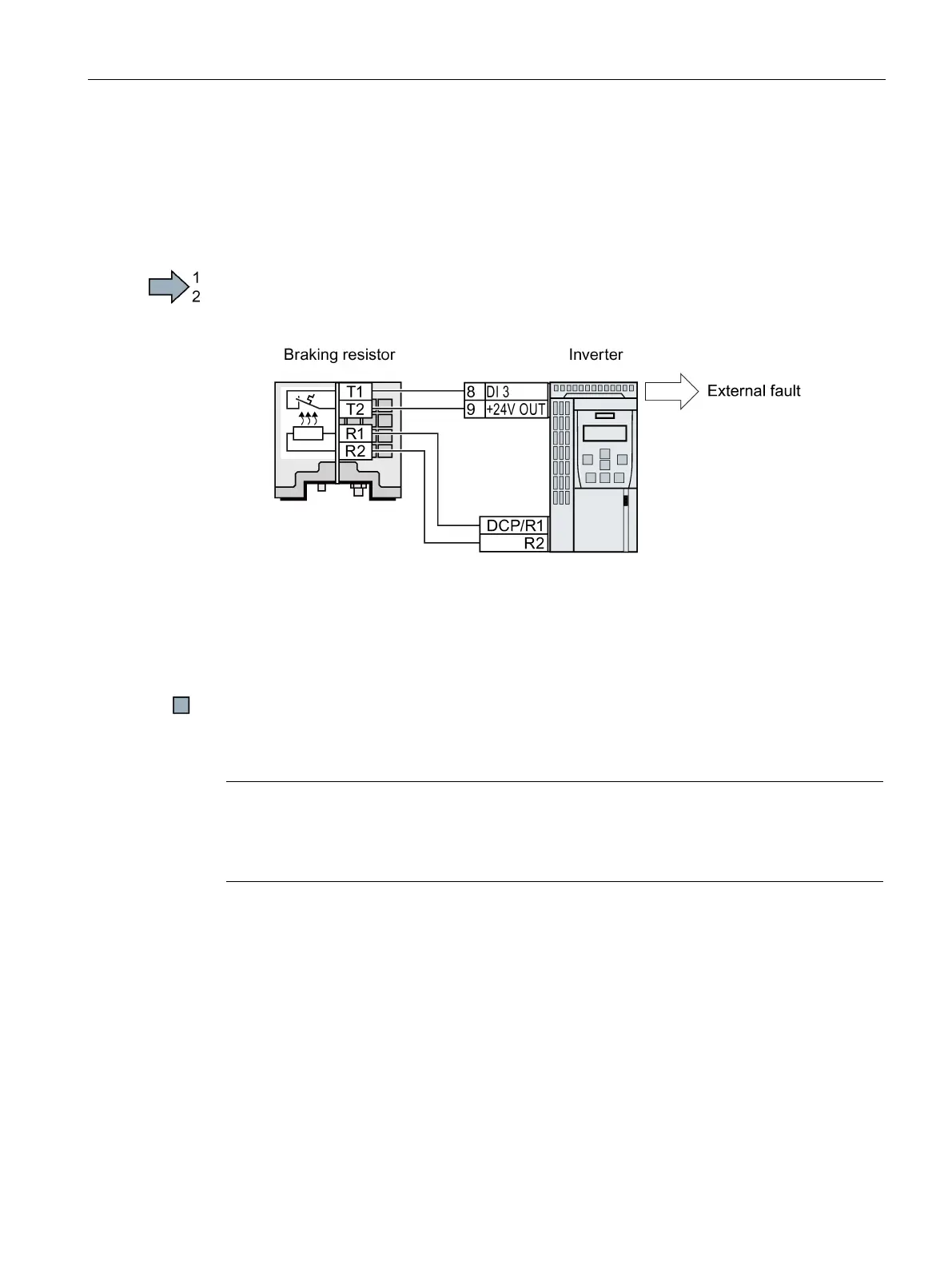
Connect the temperature contact of the braking resistor
Monitoring the temperature of the braking resistor
Procedure
Proceed as follows to monitor the braking resistor temperature:
1. Connect the temperature monitoring system of the braking resistor (terminals T1 and T2
on the braking resistor) to a free digital input at the Control Unit of the inverter.
Figure 8-6 Example: Temperature monitoring of the braking resistor via digital input DI 3 on the
Control Unit
2. When commissioning the drive, define the function of the digital input used as external
fault, using p2106.
As an example with temperature monitoring via digital input DI 3: p2106 = 722.3.
You have ensured that the temperature is monitored.
For the inverters, use the following or comparable braking resistors. The technical properties
and statements made by the manufacturer apply.
Note
Braking resistors FSD … FSF
Only use braking resistors that are UL a
pproved, and have successfully passed the
"Abnormal Operation Test" according to UL 508.
 Loading...