Installing/mounting
4.3 Mounting the Power Modules
Power Module PM240-2
Hardware Installation Manual, 12/2015, A5E33294624B AD
29
Drilling dimensions and cooling air clearances
Table 4- 2 Drilling dimensions, cooling clearances and fixing
Cooling air clearances
(mm)
FSC 343 120 6 80 100 100 4 x M5 / 3.0
FSE 509 230 11 300 350 100 4 x M6 / 10
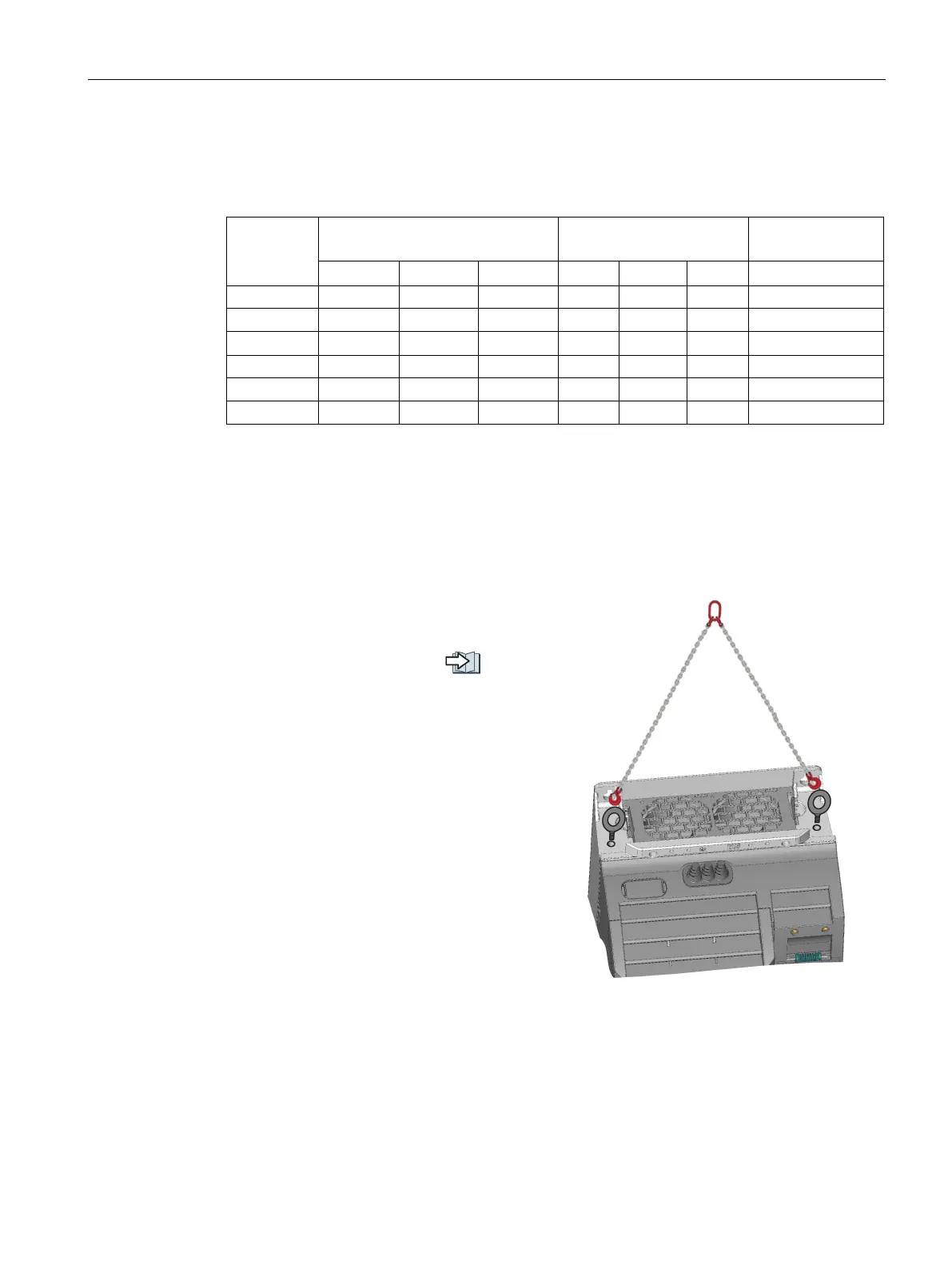
Hoisting gear FSD ... PSF
Hoisting gear
wer Modules FSD and
FSE, use crane lifting lugs and the appropr
i-
Weight of the Power Modules:
Technical data (Page 65).
 Loading...