Connecting-up
5.1 Line and motor connection
Power Module PM240-2
44 Hardware Installation Manual, 12/2015, A5E33294624B AD
Table 5- 2 Maximum permissible motor cable length (m) for inverters without filter and without EMC
Category
FSD … FSE 200 V / 400 V 200 300
FSF
Inverter in the first environment: Electromagnetic compatibility of the inverter (Page 94)
Observe the additional restrictions for inverters
6SL3210-1PE27-5UL0 and 6SL3210-1PE31-1UL0
● Motor cable length 50 m … 100 m: set the pulse frequency to 2kHz.
● Motor cable length > 100 m: the permissible base load output current decreases by 1 %
for each additional 10 m cable length.
Longer motor cables for Power Modules FSA … FSC
For EMC Category C2, second environment, cable lengths of up to 150 m are permissible, if
you use an unfiltered Power Module with an external Class B line filter and an output reactor.
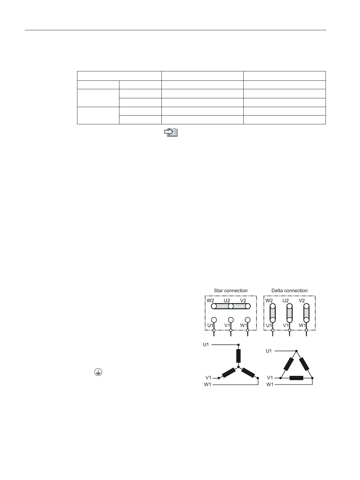
Motor connection
Star and delta connection
Siemens motors have a diagram inside t
he
terminal box showing both connection met
h-
Star connection (Y)
Delta connection (Δ)
The motor rating plate provides data about
the correct connection.
Open the terminal covers (if fitted).
Connect the protective conductor of the motor
to the
terminal of the inverter.
Connect the motor cable to terminals U2, V2
and W2.
If available, close the terminal covers of the
inverter.
connection / delta connection