Connecting-up
5.2 STO via Power Module terminals
Power Module PM240-2
Hardware Installation Manual, 12/2015, A5E33294624B AD
49
STO via Power Module terminals
Safe Torque Off (STO) for the PM240-2
-2 Power Modules, frame siz-
es FSD, FSE and FSF, you can implement the
"Safe Torque Off" safety function (STO), corr
e-
sponding to PL e according to EN 13849
-1 and
3 according to IEC61508.
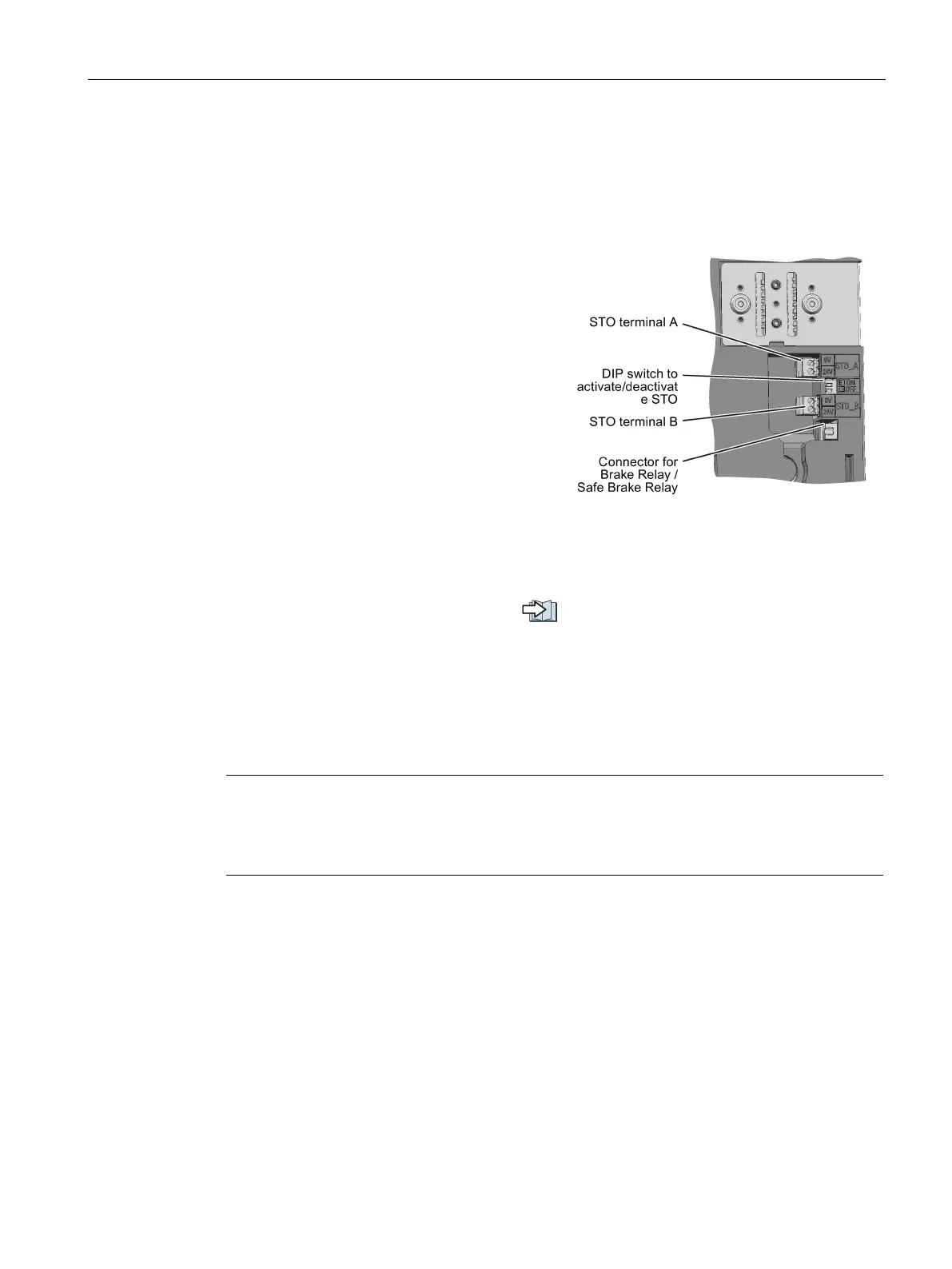
ve two terminal blocks - STO(A) and
- and two DIP switches at the front of
To be able to use the safety functions, you must
enable the terminals; you do this by setting the
two DIP switches to "1". You can only use the
safety funct
ion if both DIP switches are set to
Set both DIP switches to "0" if you do not wish to use STO. If one switch is set to 0 and the
other to 1, the inverter signals that the pulses are inhibited, and the motor does not start.
The terminals are low active.
Further information and wiring examples:
Manuals for your inverter (Page 123)
Use shielded cables with a maximum length of 30 m, a cross-section of 0.5 mm
2
… 1.5 mm
2
(20 … 16 AWG), insulated for 600 V. Connect the shield to the shield plate of the Control
Unit through the largest possible surface area.
Use conductor end sleeves, stripped length 7 mm.
Note
Safety functions via the Control Unit
You can implement the safety functions via the Contr
ol Unit independent of the safety
function "STO via the Power Module terminals".
 Loading...