Installing/mounting
4.3 Mounting the Power Modules
Power Module PM240-2
Hardware Installation Manual, 12/2015, A5E33294624B AD
27
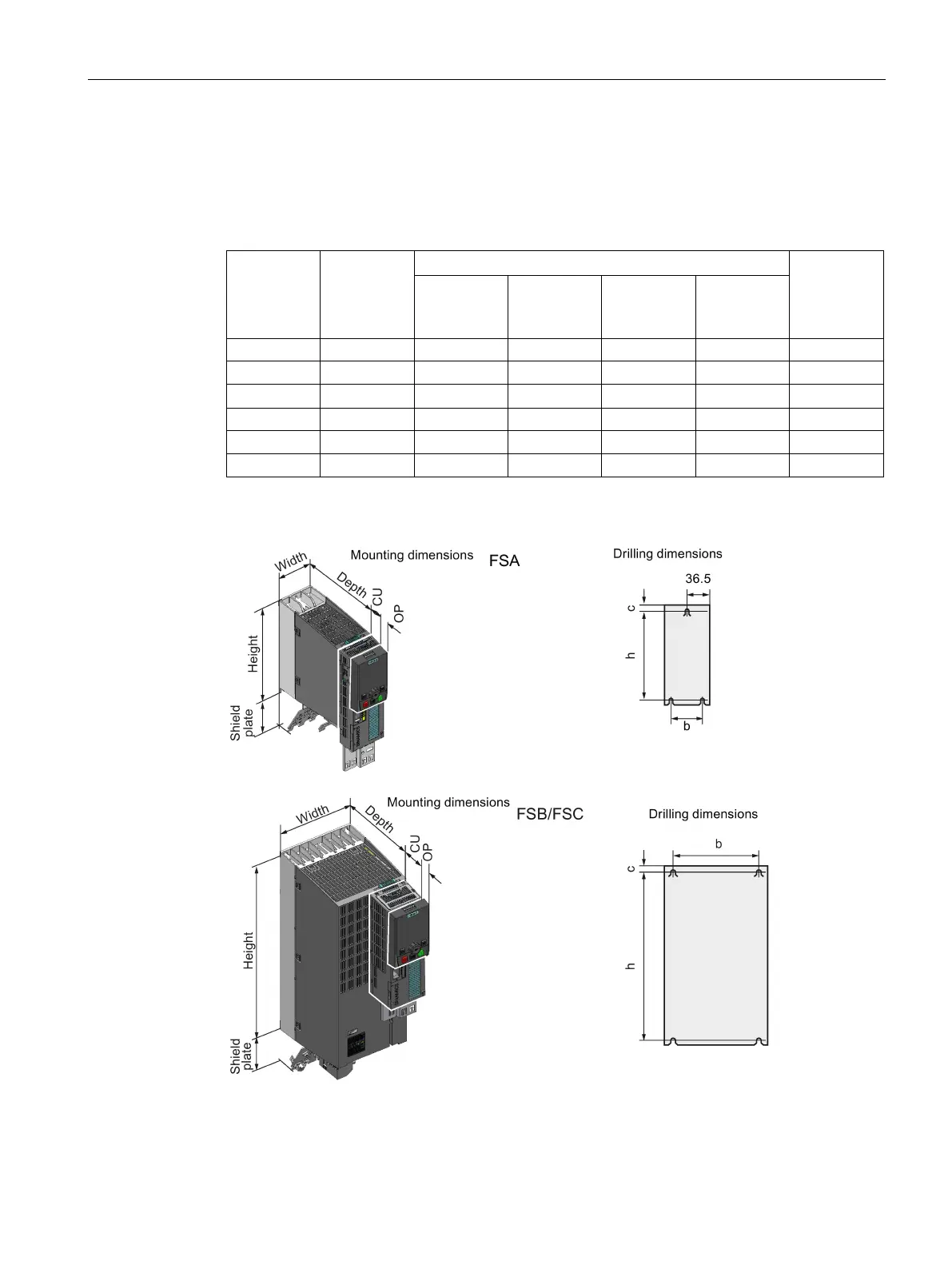
Dimension drawings and drilling dimensions for IP20 Power Modules
The following dimensioned drawings and drilling patterns are not to scale.
Table 4- 1 Mounting dimensions
Shield plate
at the bot-
tom
FSC 140 432 --- 355 77 165
The Power Modules can be mounted and operated side-by-side. For tolerance reasons, we rec-
ommend a lateral clearance of approx. 1 mm.
 Loading...