Spare parts and accessories
8.2 Optional accessories
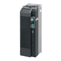
Power Module PM240-2
Hardware Installation Manual, 12/2015, A5E33294624B AD
117
Technical data of the brake relay?
Brake Relay
6SL32520BB000AA0
Safe Brake Relay
6SL32520BB010AA0
1)
Max. connection cross-section:
Switching capability of the NO
1-phase 440 VAC, 3.5 A
-
1)
External, controlled power supply required. Recommended voltage: 26 VDC
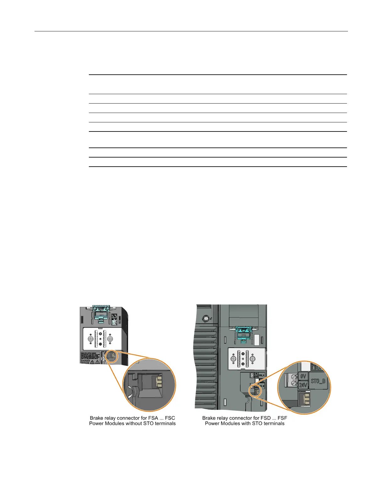
Mounting and connecting the brake relay
Installing the Brake Relay
●
: Install the Brake Relay next to the Power Module.
●
: Install the Brake Relay at the rear of the lower shield plate. Attach the Brake
Relay before you install the shield plate.
Connecting the Brake Relay to the inverter
The connector for the Brake Relay is located at the front of the Power Module. Lay the cable
harness for the Brake Relay in the cable routing.
 Loading...