Connecting-up
5.1 Line and motor connection
Power Module PM240-2
46 Hardware Installation Manual, 12/2015, A5E33294624B AD
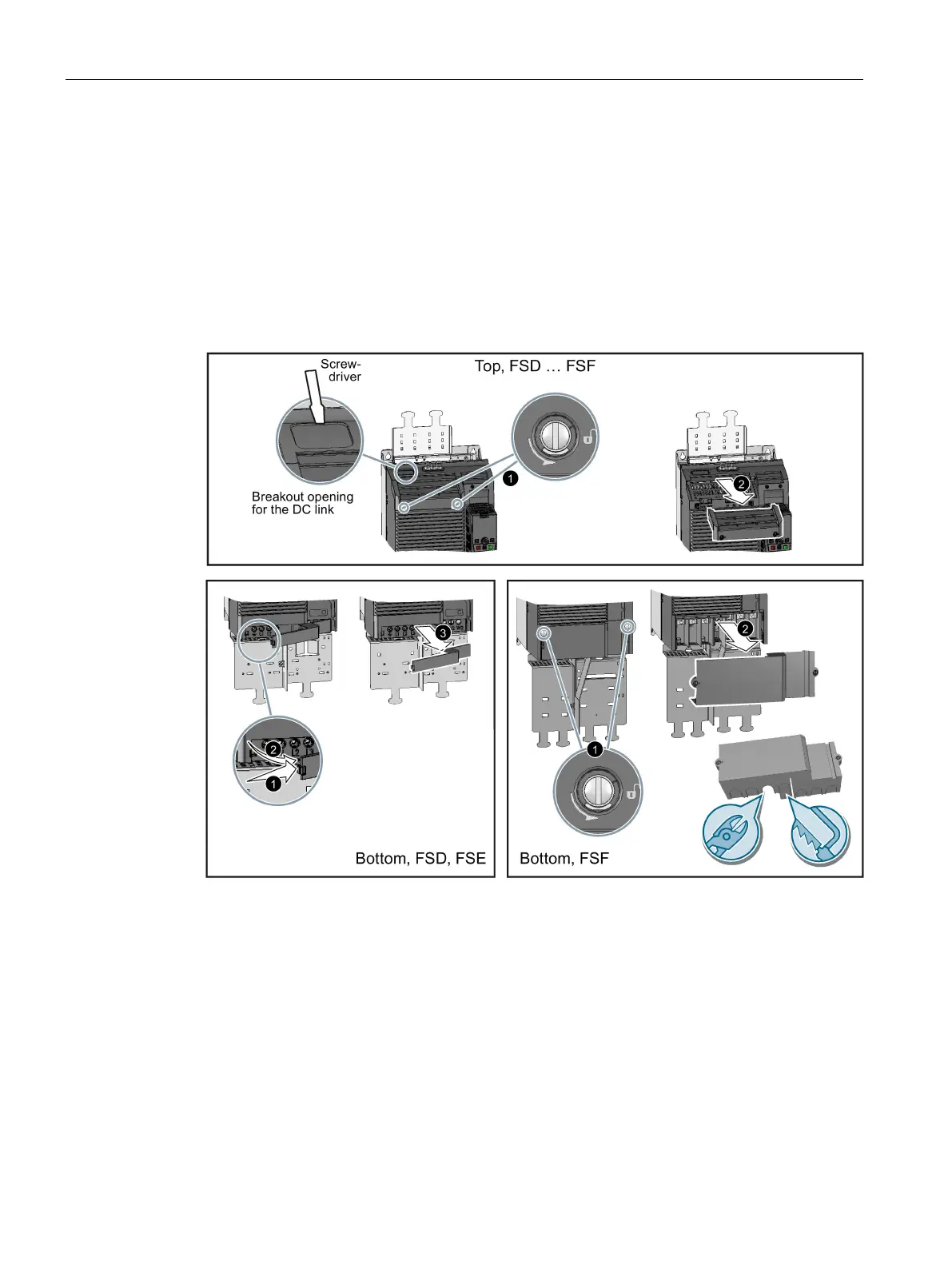
Connecting terminals for FSD … FSF
Covers protect the connections for the line supply, motor, DC link and braking resistor and
prevent coming into contact with live components. The following diagram shows how you
can remove the covers. The covers are attached in the inverse order.
The connections for the motor (FSD and FSE) and braking resistor (FSD … FSF) are also
protected against contact by a blanking plug. Release the two clamping screws and remove
the blanking connector before you connect the motor cable and/or the braking resistor.
Use a suitable tool to knock out the openings for the power connection. We
we recommend side cutters or a saw with a fine saw blade.