Connecting-up
5.3 EMC-compliant installation
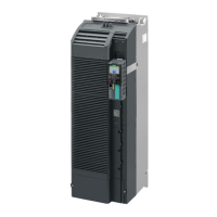
Power Module PM240-2
52 Hardware Installation Manual, 12/2015, A5E33294624B AD
● Connect the shields to the grounded enclosure at both ends with a good electrical
connection through the largest possible surface area.
● Route incoming and outgoing cables/conductors within a zone (where unshielded single-
conductor cables are used), twisted or in parallel and as close to one another as possible.
● Ground any unused conductors of signal and data cables at both ends.
● Signal and data cables should enter the cabinet only at one point (e.g. from below).
Cables outside the control cabinet
● Route the power cables of the drive so that there is a minimum clearance of 25 cm to
signal and data cables.
● Use shielded motor cables.
● Use shielded signal and data cables.
● Route the shielded motor cable separately from the cables to the motor temperature
sensors.
● For shielded cables, only use cables with finely-stranded, braided shields.
● Connect the shield at the grounded enclosure as well as at the EMC shield bar.
– Connect the shields to the grounded enclosures through a large surface area at both
ends of the cables to establish a low ohmic connection. Attach the shields to the
appropriate EMC shield bars.
– Immediately after the cable enters the cabinet, connect the cable shields to the EMC
shield bar through a larger surface area to establish a low ohmic conduction.
● If possible, always route the cable shields without any interruptions.
● Only use metallic or metallized connectors for the plug connections for shielded data
cables (e.g. PROFIBUS connection).
You can find additional information about the EMC installation guidelines under
(http://support.automation.siemens.com/WW/view/en/60612658):
 Loading...


