System Components
SICAM RTUs, SICAM AK 3 User Manual 153
DC2-028-2.03, Edition 07.2016
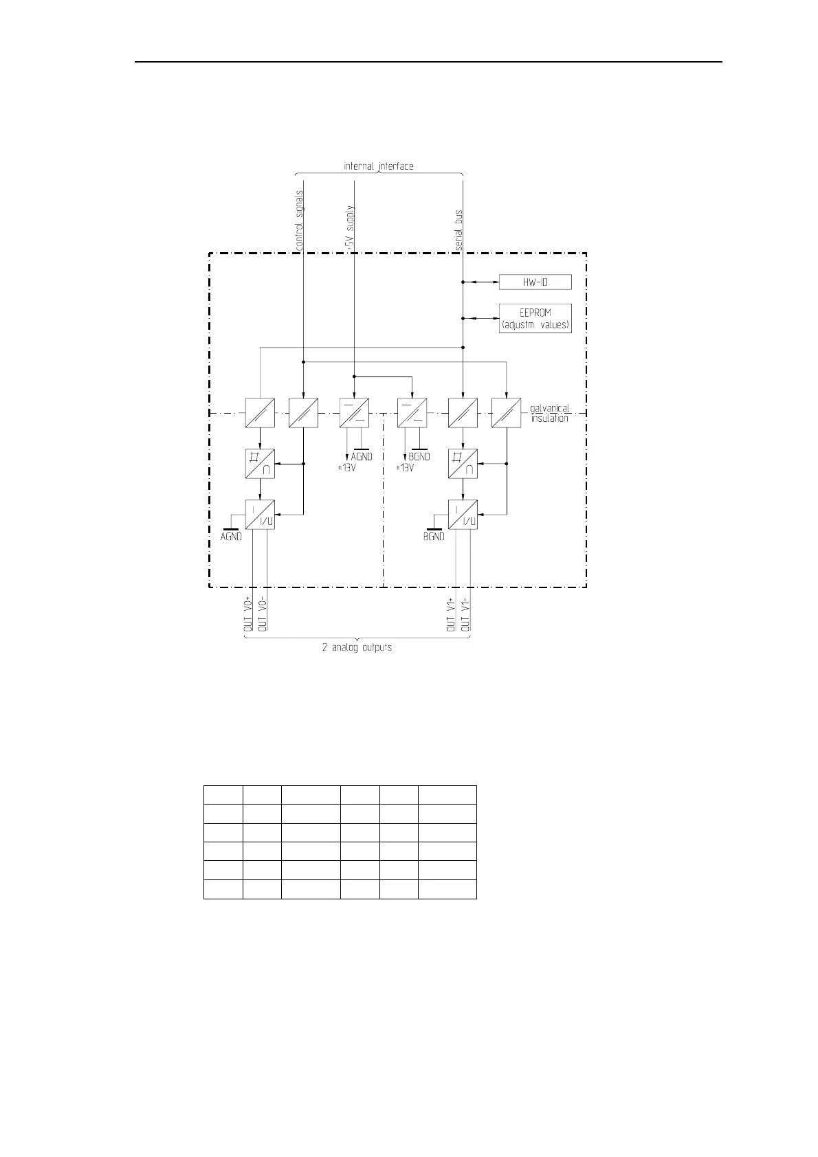
2.7.4.1 Block Diagram
2.7.4.2 Connector to Carrier Module
The pin assignment of the connector is described as follows:
Pin Alias Signal Pin Alias Signal
1 I/O 0 2 I/O 1
3 I/O 2 OUT V0+ 4 I/O 3 OUT V0-
5 6
7 I/O 4 8 I/O 5
9 I/O 6 OUT V1+ 10 I/O 7 OUT V1-
The abbreviations have the following meaning:
OUT V0+, OUT V0- = analog output 0
OUT V1+, OUT V1- = analog output 1
 Loading...


