Process interfacing via an automation system (PLC, PC)
9.5 Controlling the I/O interface "DI/DQ"
SIMATIC MV500
152 Operating Instructions, 06/2018, C79000-G8976-C494-01
Controlling the I/O interface "DI/DQ"
Control signals
Note
Range of functions depends on the settings in WBM
Note that the control of the reader via the digital inputs/outputs depends on the settings in
the menu "Settings > Communication > Digital I/O" of the WBM.
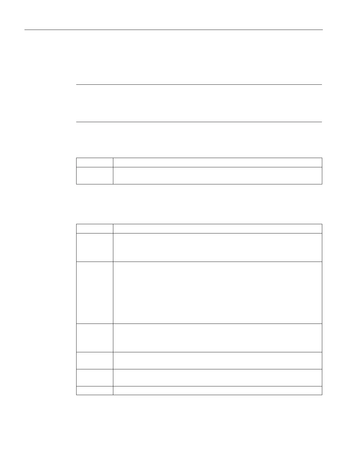
Table 9- 51 Assignment of control bytes (input signals)
TRG Trigger
Processing starts on a positive edge.
The optical reader has two freely assignable digital outputs. The following table provides an
overview of the possible output signals.
Table 9- 52 Assignment of status byte (output signals)
IN_OP In operation
• 0: Error message is displayed.
• 1: Optical reader functioning, no error
TRD Trained
• In run:
– 0: Selected program is not saved.
– 1: Selected program has been saved.
• With Save program (TRN = 1):
– 0: Save program active.
– 1: Acknowledgment signal (RDY = 0)
RDY Ready:
• 0: Startup of the optical reader or optical reader in STOP
• 1: Optical reader in run
READ Processing result
Code was localized and decoded.
MATCH Processing result
Code matches the trained code.

 Loading...


