Network and system integration
4.6 System configuration with CM and RFID reader
SIMATIC MV500
58 Operating Instructions, 06/2018, C79000-G8976-C494-01
● The result output of the optical reader takes place via the RS232 interface.
● The optical reader is triggered either via digital I/O, RS232 or via the built-in auto-trigger
function.
● A PC/programming device is connected via Ethernet to allow adjustment of the device.
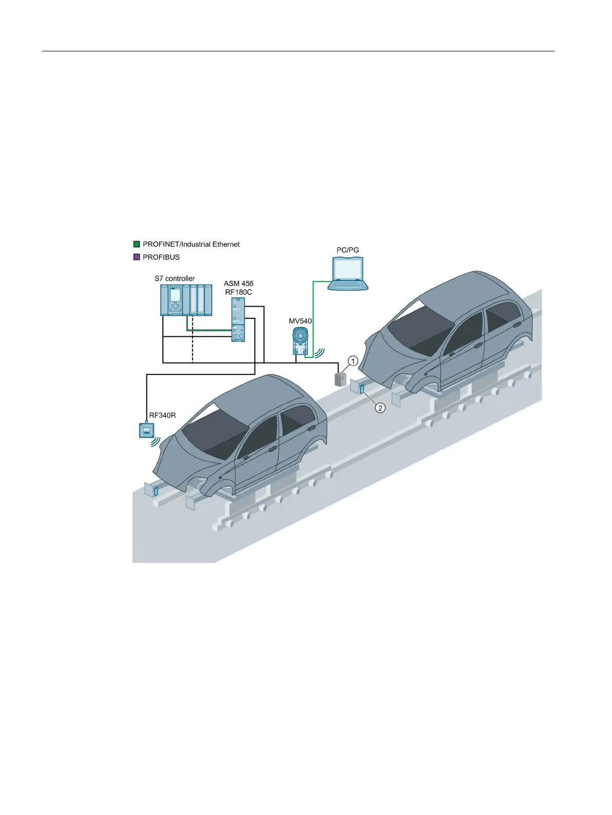
System configuration with CM and RFID reader
Optical sensor or light barrier (for trigger signal)
Figure 4-5 Example: System configuration of optical reader with RFID reader on a communication
module
● In mixed operation with an RFID reader, e.g. from the SIMATIC RF300 series, the optical
reader can be connected to a communication module and operated.
● Both the optical reader and the RFID reader are integrated in STEP 7 by the Ident profile
block.
● A PC/programming device is connected via Ethernet to allow adjustment of the device.

 Loading...


