Hardware section
2.3 Wiring
S7-1500
Getting Started, 05/2014, A5E03981761-AC
25
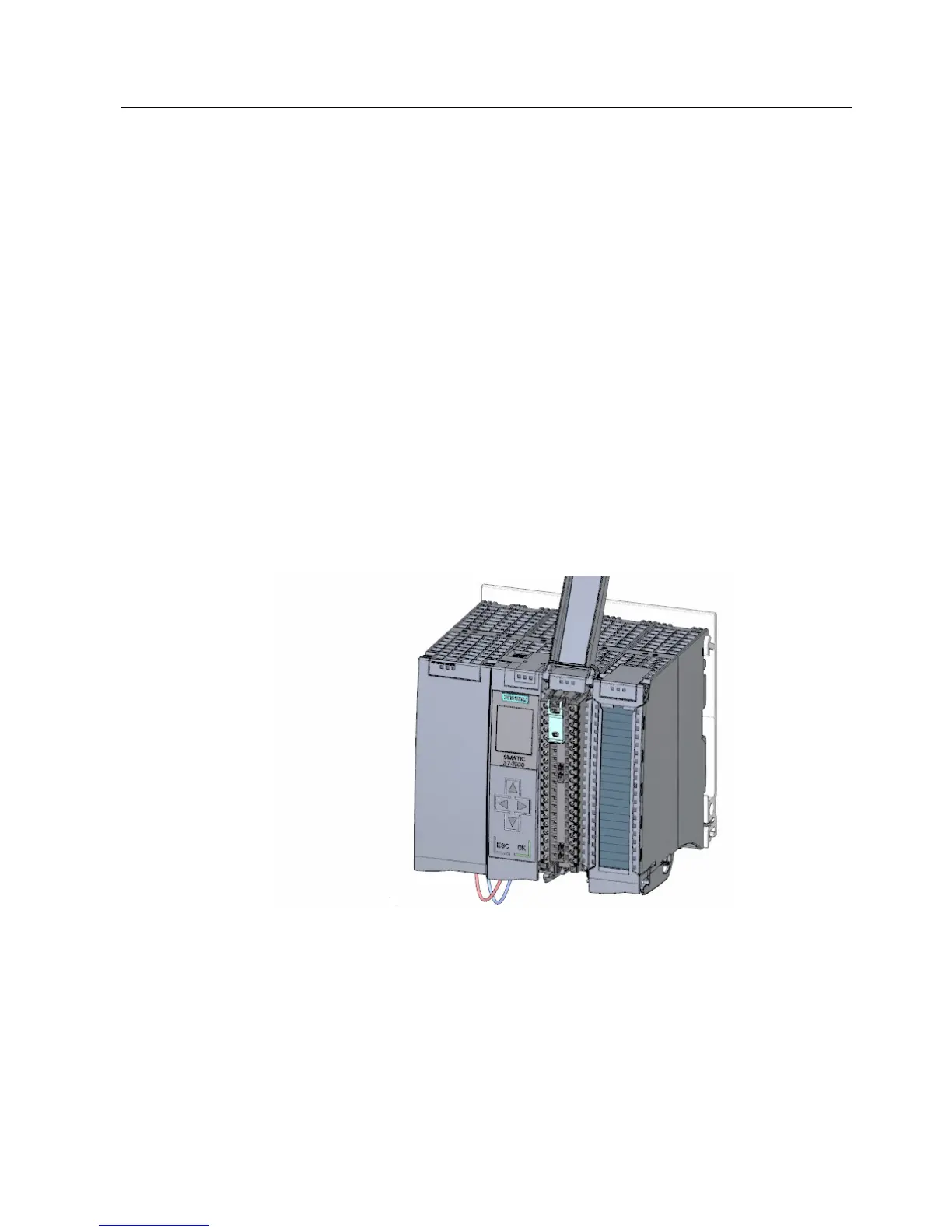
Potential bridge circuits
Application of the potential bridge circuits
If you want to supply the load groups with the same potential (non-isolated), use the potential
circuit bridges supplied for the front connector. This means that you avoid having to wire a
clamping unit with two wires.
Use the terminals 40 (M) and 39 (L+) on the front connector to loop the potential to the next
module.
Wiring the digital input module
Procedure
1. Insert the front connector into the pre-wiring position. There is no electrical connection
between the front connector and the module in the pre-wiring position.
 Loading...


