Operation
2–29
IP244
C79000–B8576–C859–02
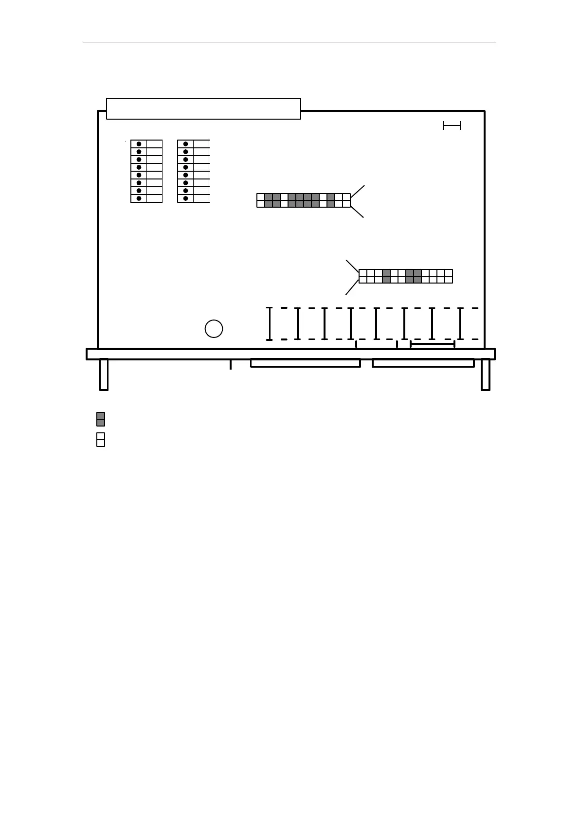
Fig. 3.4/2 Settings for resistance thermometer Pt 100
= Jumper inserted
= Jumper not inserted
1 12
12 1
A 76
1
2
3
4
5
6
7
8
A 77
BA
112
X 4
DQ
X 3
AI
X 5
L+
F 2
1
12
X 9
X 8
X 6
X 7
offon offon
Bus connector X1
X1 Backplane connector
X3 Front connector for analog inputs
X4 Front connector for digital outputs
X5 Connections for load voltage L+
F2 Fuse for DQ (load voltage L+)
A76 Module address, ADB 8–11 (DIL switch); see Section 3.4.1
A77 Module address, ADB 5–7 (DIL switch); see Section 3.4.1
A27 Interrupt setting switch (DIL); not fitted
X6/7 Jumpers; see top of next page
X8/9 Jumpers; see bottom of next page
A–B Jumper must be soldered in (only for test purposes)