Operation
IP244
C79000–B8576–C859–02
2–30
60
Hz
50
Hz
Thermal e.m.f.
Voltage
Current
Measurement
51.2 mV
input
sensitivity
Channel 15 for
general
measurement time
acquisition
Channel 15 for
compensation with
Pt 100 3Ćwire
(*)
Open Inserted
X6/X7
1
2
3
4
5
6
7
8
9
10
11
12
1
2
3
4
5
6
7
8
9
10
11
12
(*)
(*)
(*)
(*)
(*)
(*)
(*)
Not used
See Section 3.4.2
Test points (must be inserted)
Selection of the
integration time
20 ms/ 16
2/
3
ms
see Section 3.4.3
1
2
3
4
5
6
7
8
9
10
11
12
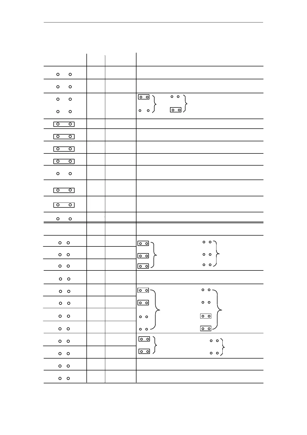
(*) This setting is required for the module to function perfectly and must not be changed (the test points are
required to test the module). Jumper A-B (for test purposes) must be soldered in.
(Fig. 3.4/1 and Fig. 3.4/2).
1
2
3
4
5
6
7
8
9
10
11
12
X8/X9
No BASP evaluation when jumper inserted
Significance of the jumpers
Pt 100
Resistance
sensor
4Ćwire
connection
Jumper
C
Jumper
D
Standard setting 244Ć3AA22
Not used
As delivered User configuration
Test points (inserted = 64 messages)
Test points (must be inserted)
Test points (must be inserted)
Standard setting 244Ć3AA22
Standard setting 244Ć3AA22
Open Inserted
51.2 mV
input
sensitivity
Not used
Not used