INSTALLATION
3-8
Hardware
and Installation User Manual
3.3.3 Selecting
Ladder Memory Pr
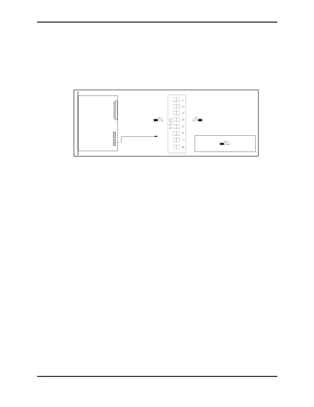
otection — TI525 Models
Switch
4 on DIP 2 prevents modifications to the RLL program in ladder memory
.
Your
programming unit refers to this switch as a keylock.
Refer
to Figure 3-6. Turn switch 4 ON to prohibit changes to the program. T
urn
switch
4 OFF to permit program editing.
DIP
2
ONOFF
Position not
Selected
Position
Selected
Push Down
L-Memory
protect of
f
L-Memory
protect on
Figure 3-6 Switch Settings — TI525 L-Memory Protection
Turning the L-memory protect switch on does not prevent
forcing I/O, changing variable memory, or switching the PLC
from
PROGRAM to RUN mode. These actions may be initiated
with a programming device connected to the PLC, or a special
function I/O module designed for this type of interface to the
PLC,
e.g., a Network Interface Module.
The RLL can also be changed through a special function
module, even when the memory protection is enabled with the
keylock. Do not depend upon this switch to prevent personnel
from
interrupting your process.
Artisan Scientific - Quality Instrumentation ... Guaranteed | (888) 88-SOURCE | www.artisan-scientific.comArtisan Technology Group - Quality Instrumentation ... Guaranteed | (888) 88-SOURCE | www.artisantg.com

 Loading...


