INSTALLATION
3-26
Hardware
and Installation User Manual
6. Use
14 A
WG solid or stranded wire for connection to the power
source; use of smaller wire is not recommended. If stranded wire is
used, the wire should be twisted and tinned.
7.
Insert the green ground wire into the connector labeled “ground.”
8.
Insert the black AC line and white AC neutral wires into the power
supply wire connectors labeled “AC line” and “AC neutral,”
respectively.
Connecting the power supply leads to the
wrong terminals creates a potential shock
hazard that could cause damage to
equipment or injury to personnel. Be sure
that the polarity on all power supply leads is
correct.
9. After
inserting the wires, secure them by tightening the terminal
block screws.
10.
Enable power
.
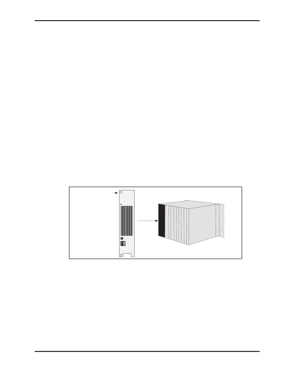
Bezel screws
Figure 3-19 Location of Power Supply in Base
The base power budget is determined from the power provided by the base
power supply and the requirements of the particular modules used. When
determining
the I/O system layout, do not exceed the maximum power available
from the power supply. The total power requirement for all modules drawing
power
from a Series 505 base must be less than or equal: 55 W at +5 VDC and
3.75 W at –5 VDC.
Artisan Scientific - Quality Instrumentation ... Guaranteed | (888) 88-SOURCE | www.artisan-scientific.comArtisan Technology Group - Quality Instrumentation ... Guaranteed | (888) 88-SOURCE | www.artisantg.com
 Loading...


